Auxiliary drive shaft connection on reel mower cutting unit

a technology of auxiliary drive and cutting unit, which is applied in the direction of mowers, agriculture tools and machines, etc., can solve the problems of difficult disconnection or reconnection of the attachment from the auxiliary drive output shaft, and the auxiliary drive may need to be partially or completely disassembled, so as to simplify the disconnection or reconnection of the attachment. , the effect of shortening and simplifying the process

Active Publication Date: 2010-01-19
DEERE & CO
View PDF21 Cites 8 Cited by
  • Summary
  • Abstract
  • Description
  • Claims
  • Application Information

AI Technical Summary

Benefits of technology

[0008]The present invention shortens and simplifies disconnection or reconnection of an attachment from an auxiliary drive output shaft, permits adjusting the attachment's position or depth of engagement, and maintains positive centering of the auxiliary drive output shaft with the attachment.

Problems solved by technology

However, disconnecting or re-connecting the attachment from the auxiliary drive output shaft is a difficult task.
As a result, the auxiliary drive may need to be partially or completely disassembled.

Method used


Image

  • Auxiliary drive shaft connection on reel mower cutting unit
  • Auxiliary drive shaft connection on reel mower cutting unit
  • Auxiliary drive shaft connection on reel mower cutting unit

Examples


Embodiment Construction

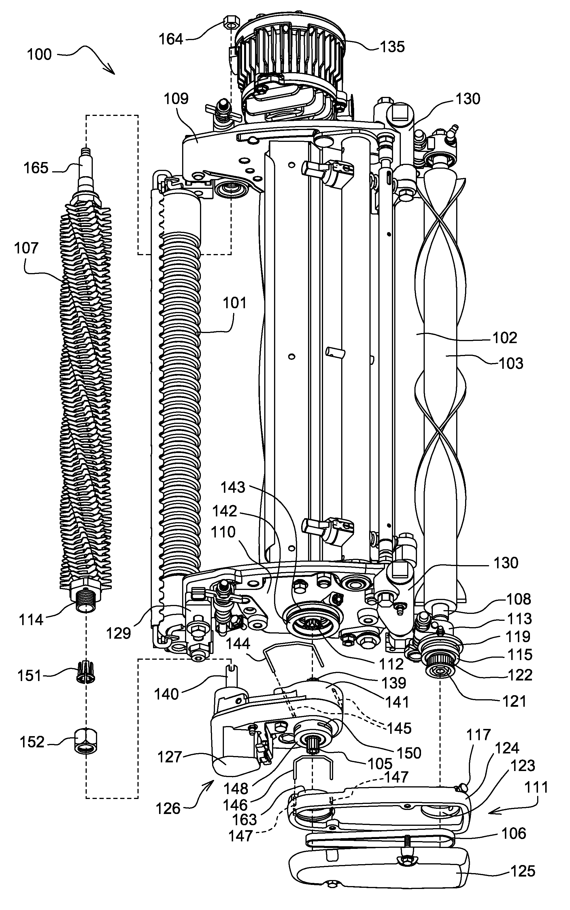
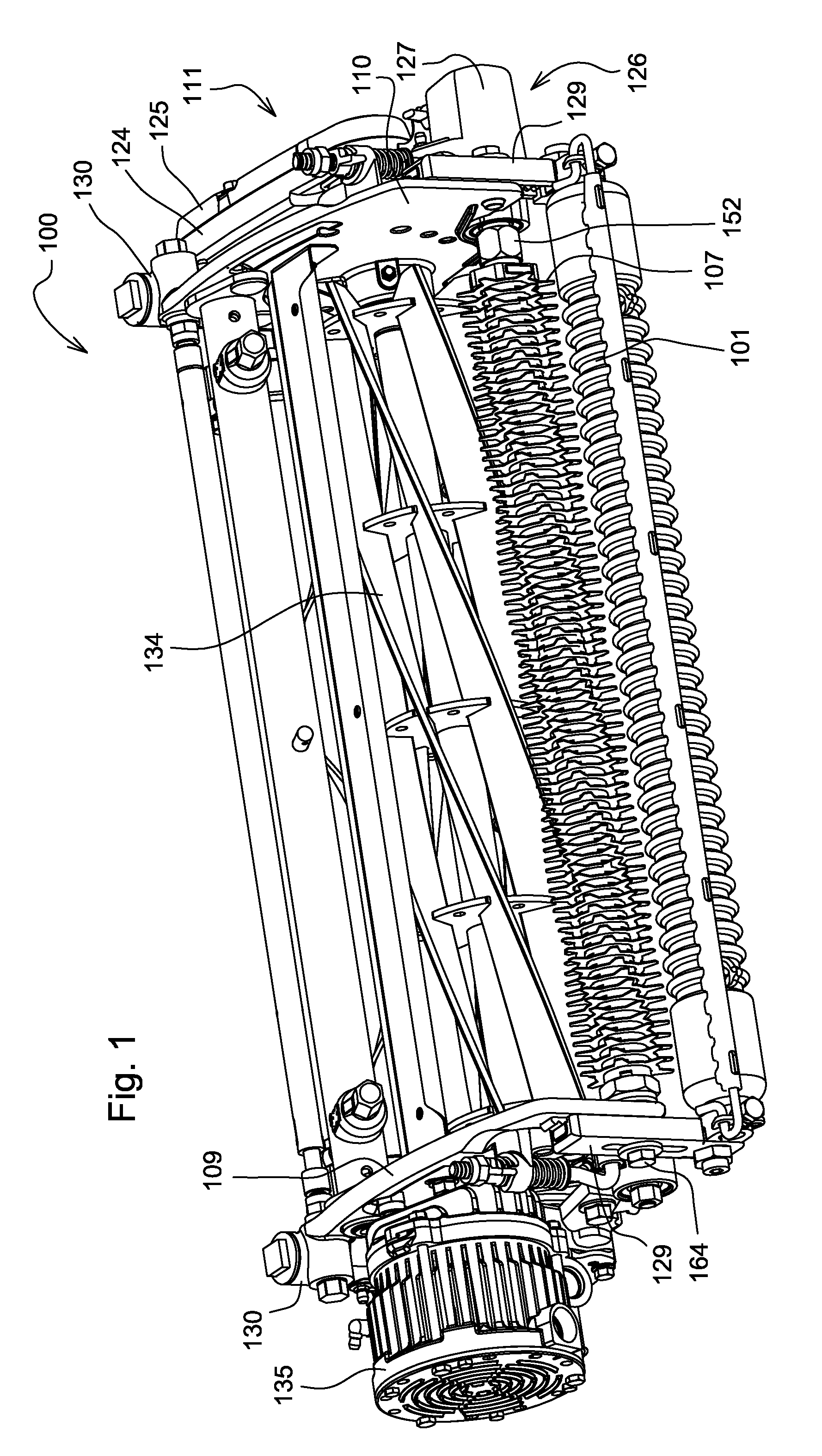
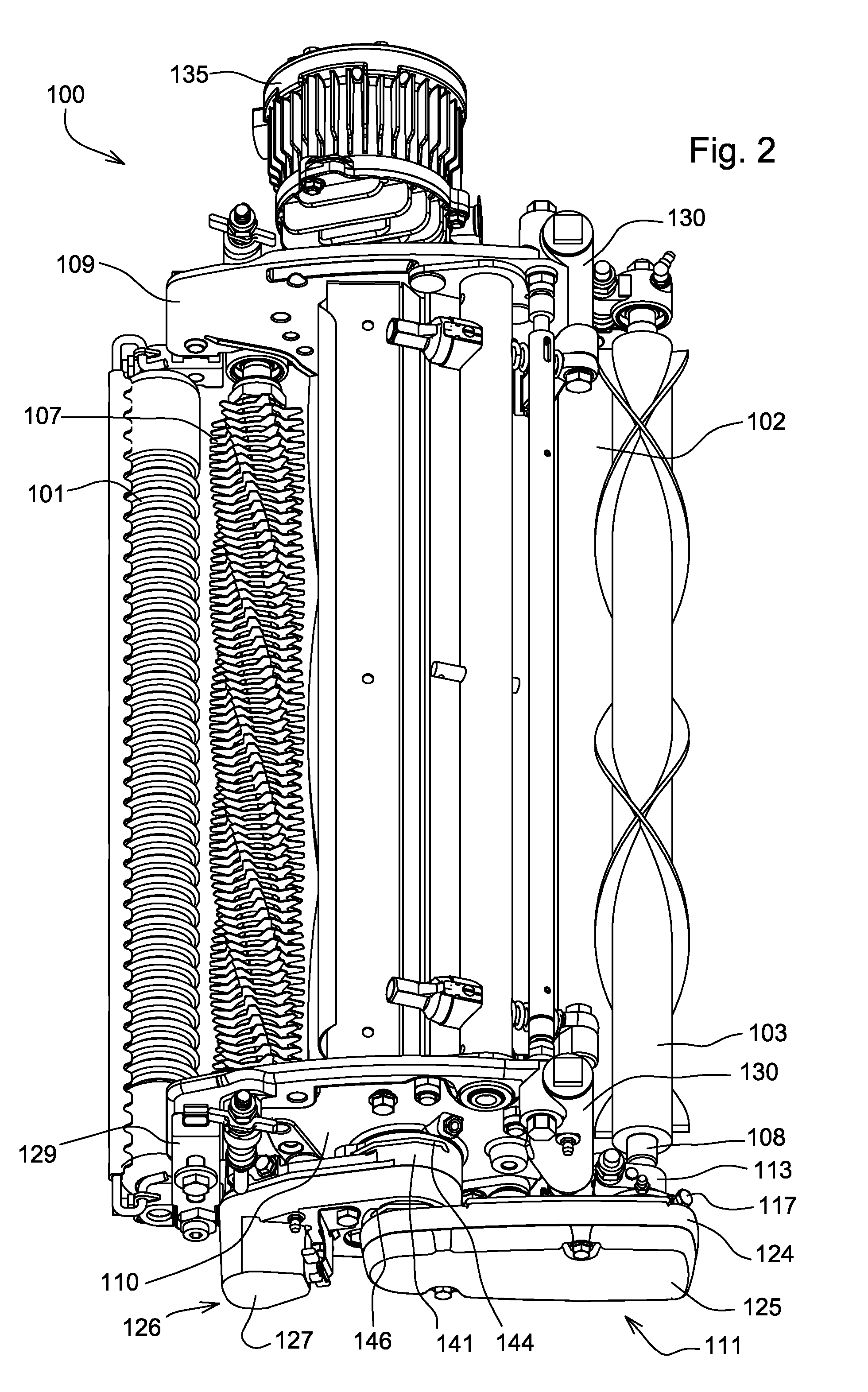
[0021]In the embodiment shown in FIGS. 1-8, reel mower cutting unit 100 has front and rear rollers 101, 102 that roll in contact with the ground and support the cutting unit during mowing operations. The reel mower cutting unit includes a generally cylindrical reel 134 having a plurality of blades on cutting reel shaft 104 to rotate about the cutting reel shaft's laterally extending horizontal axis. The cutting reel shaft may be rotated with electric motor 135 or, alternatively, by a hydraulic motor. As the blades rotate they pass in close proximity to bedknife 137 positioned between side panels 109, 110 of the cutting unit frame. The blades and bedknife interact to cut grass with a shearing action as the cutting unit is propelled forward. To adjust the cutting height, front and rear roller adjustment mechanisms 129, 130 may be used to raise and lower the front and rear rollers.

[0022]In the embodiment of FIGS. 1-6 and 8, two attachments are shown on reel mower cutting unit 100: cond...


PUM


Abstract

An auxiliary drive mounted to a reel mower cutting unit includes a cutting reel shaft rotated by a motor and having a horizontal axis, an auxiliary drive housing positioned adjacent the reel mower cutting unit and pivotable on the axis of the cutting reel shaft, an auxiliary drive input shaft engaged to the cutting reel shaft, and an auxiliary drive output shaft coaxially engaged to an end of an attachment outside the auxiliary drive housing by inserting one of the auxiliary drive output shaft and the attachment end through a collet and tightening a nut over the collet. A transverse pin in one of the output shaft and the attachment end may be engaged by a split end in the other of the output shaft and the attachment end.

Description

FIELD OF THE INVENTION[0001]This invention relates generally to auxiliary drives mounted to reel mower cutting units, and specifically to auxiliary drives for attachments such as a conditioner or roller power brush rotatably mounted on a reel mower cutting unit.BACKGROUND OF THE INVENTION[0002]Grass mowing machines with reel mower cutting units are used on golf courses and other turf areas that require grass to be cut very accurately. The cutting units are typically rolled across the surface of the ground by a powered vehicle. The cutting units include a generally cylindrical reel with a plurality of blades that rotate in close proximity to a stationary bedknife fixed with the frame of the cutting unit. Grass is cut by a shearing action between the bedknife and the rotation blades of the reel.[0003]Attachments on reel mower cutting units may be used to improve the quality of the cut, performance, and other turf grooming features. The attachments, such as conditioners, roller power b...

Claims


Application Information

Patent Timeline
Patent Type & Authority Patents(United States)
IPC IPC(8): A01D34/53
CPCA01D34/43A01D34/62A01D43/00
Inventor RINHOLM, BRENT G.THIER, RICHARD D.
Owner DEERE & CO
Why Eureka
Try Eureka