
Breakaway hose coupling with a magnetic connection

a technology of magnetic connection and coupling, which is applied in the direction of couplings, water supply installation, liquid transfer devices, etc., can solve the problems of variation in the tension force required to separate or pull the coupler bodies apart, annular coil spring connection also requires significant axial compression force, and achieves the effect of simplifying the reconnection or recoupling of the coupler bodies

Active Publication Date: 2007-08-07
GILBARCO
View PDF7 Cites 100 Cited by
  • Summary
  • Abstract
  • Description
  • Claims
  • Application Information

AI Technical Summary

Benefits of technology

[0006]In the illustrated embodiment, the magnet system includes circumferentially spaced magnets formed of rare earth materials, and the magnets are slightly spaced from the annular strike member when the coupler members are connected. Both the magnet system and the strike member are protected after separation of the coupler bodies by interfitting annular protective or cylindrical semi-rigid covers or sleeves. The magnetic coupling system of the invention also provides for conveniently reconnecting or recoupling the coupler bodies.

Problems solved by technology

While the use of shear pins is the least expensive means for releasably connecting the coupler bodies, trained repair personnel and significant time is required to replace the shear pins after the coupler bodies have been separated.
However, the use of annular coil springs results in variation in the tension force required to separate or pull the coupler bodies apart.
In addition, the annular coil spring connection also requires a significant axial compression force to rejoin or reconnect the coupler bodies.
It has also been determined that the hydraulic line shock or hammer effect produced in the fuel supply lines or hoses during shut off of the fuel supply by the dispensing nozzles results in wear of the shear pins and coil springs.
This wear reduces the tension force required to separate the coupler bodies and thus requires periodic maintenance or replacement of the pins or springs.

Method used


Image

  • Breakaway hose coupling with a magnetic connection
  • Breakaway hose coupling with a magnetic connection
  • Breakaway hose coupling with a magnetic connection

Examples


Embodiment Construction

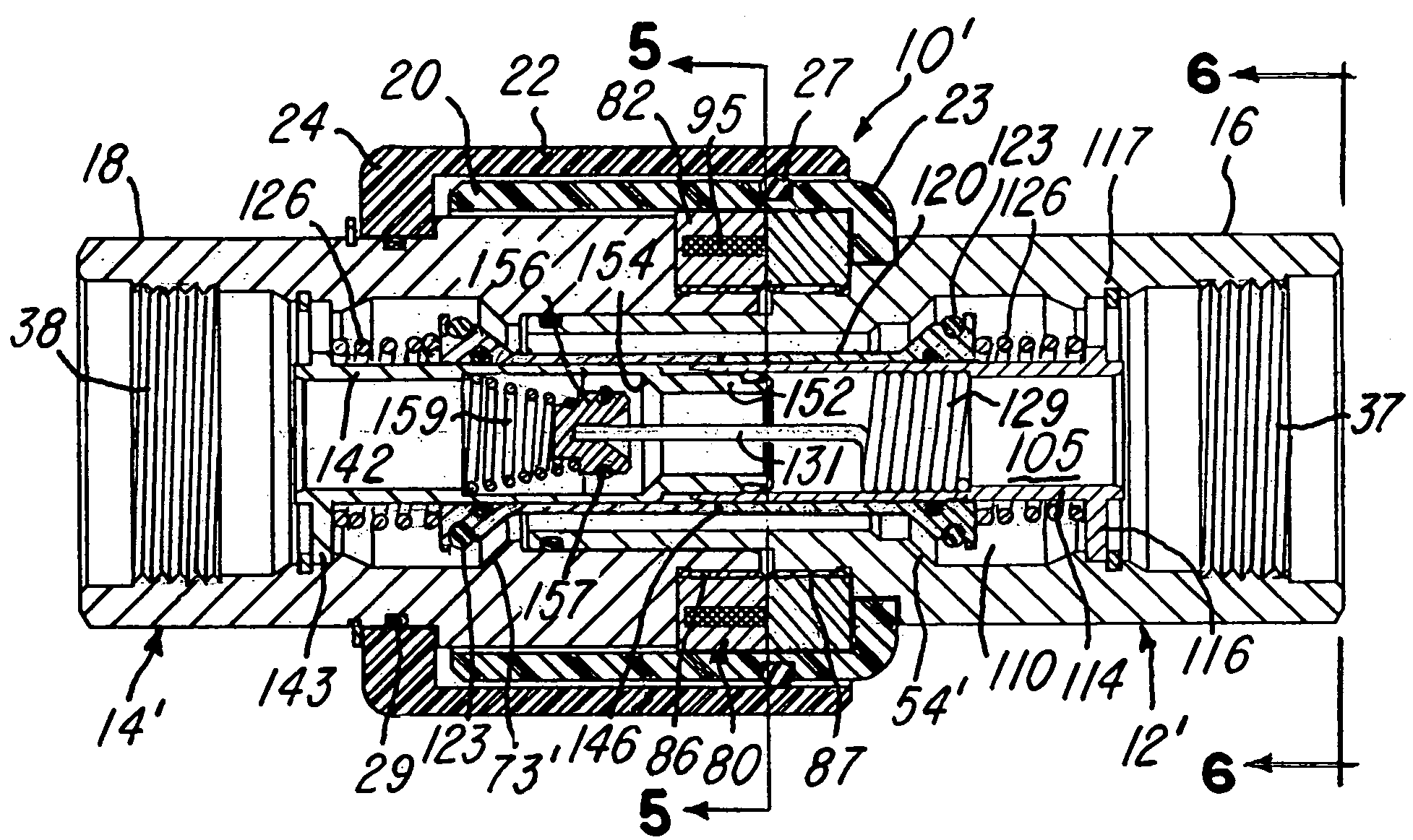
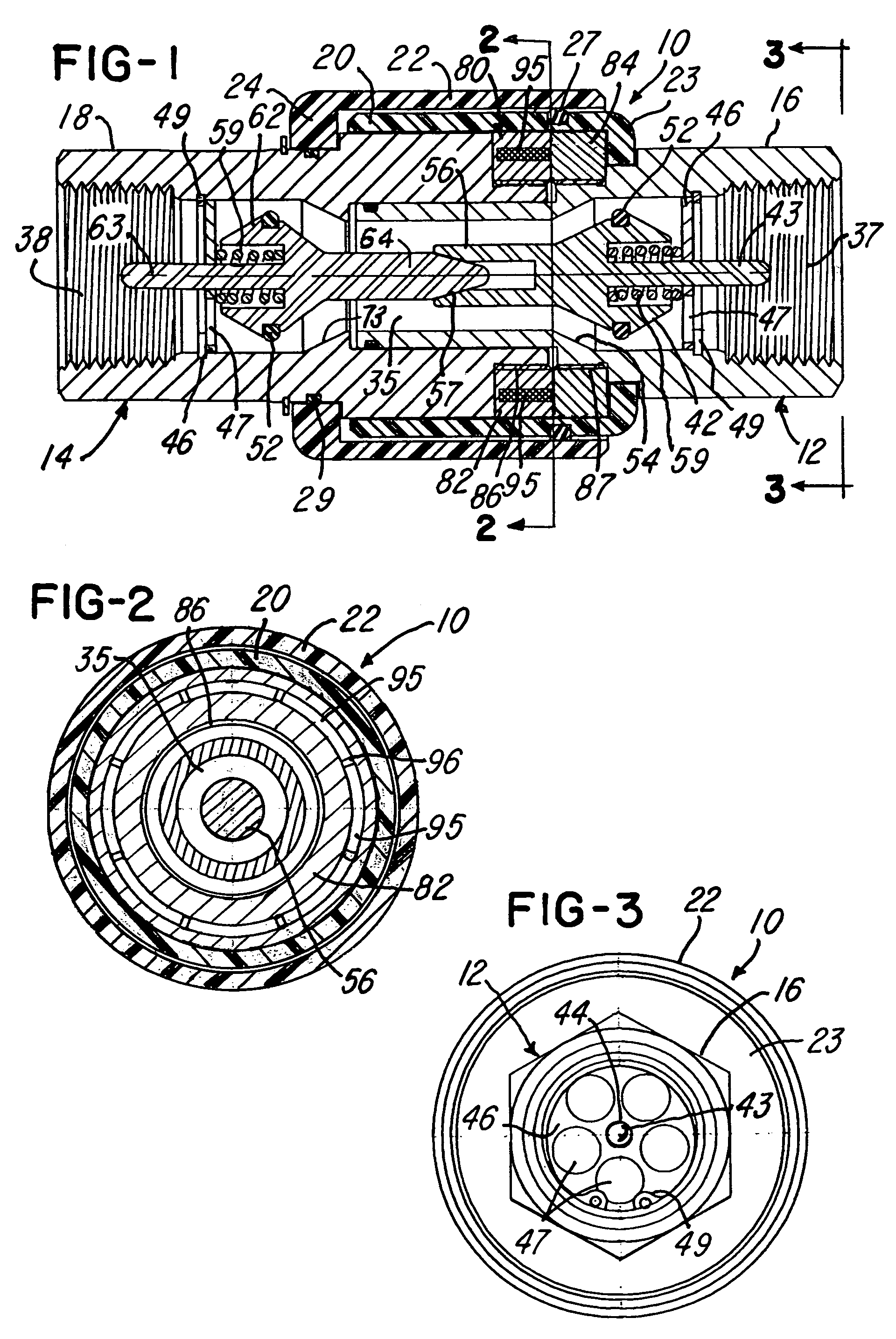
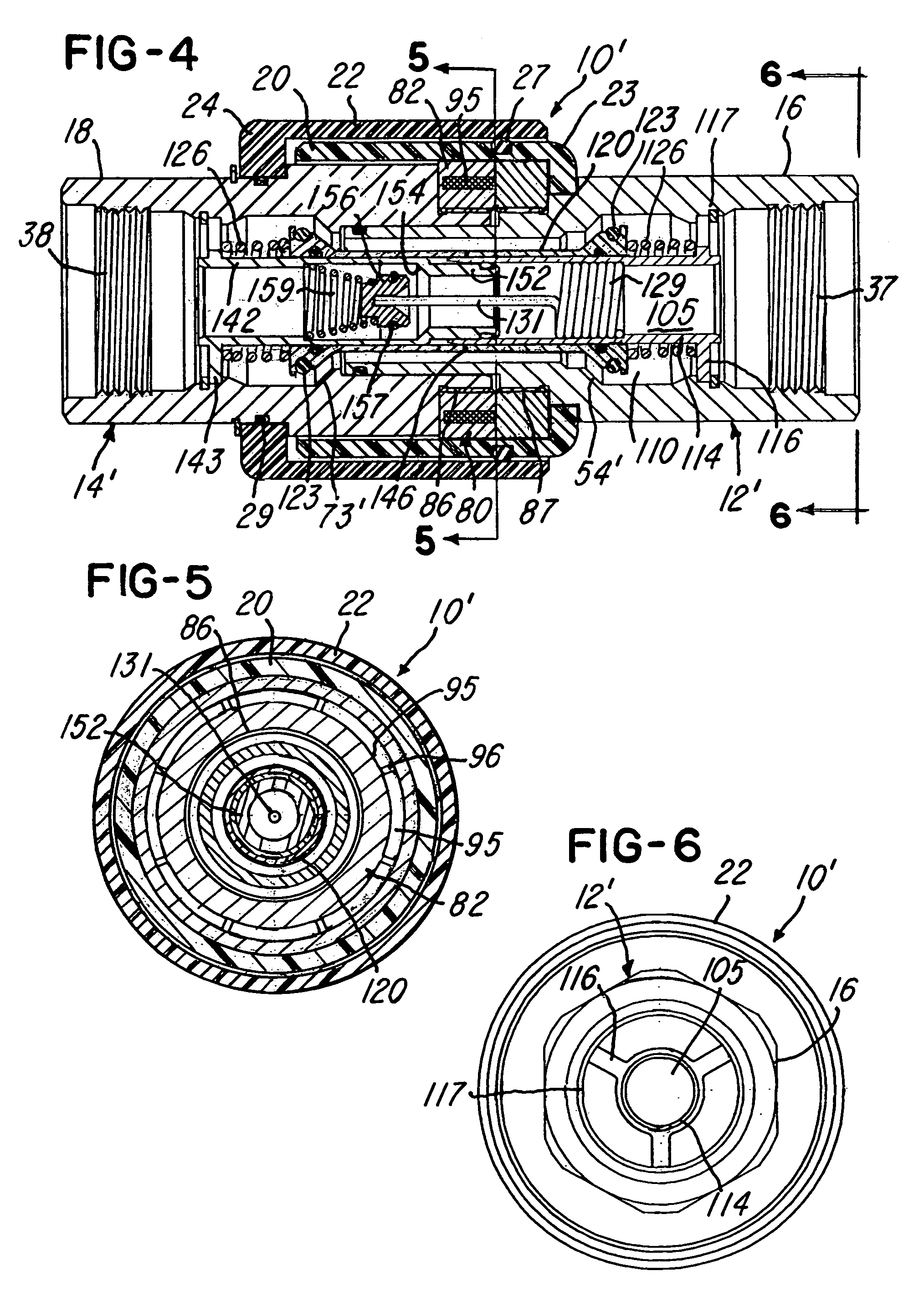
[0014]FIG. 1 illustrates a breakaway hose coupling 10 which includes a tubular male coupler body or body member 12 and a tubular female coupler body or body member 14 which are formed of a metal such as aluminum and have corresponding hexagonal outer end surfaces 16 and 18, respectively. As shown in FIG. 1, the body members 12 and 14 are in their coupled or connected position and are partially surrounded by interfitting annular or cylindrical sleeves or covers 20 and 22 molded of a semi-rigid plastics material such as nylon. The male cover 20 has an end portion 23 which mounts on the body member 12 against an annular shoulder, and the cover 22 has an end portion 24 which mounts on a cylindrical surface of the body member 14. The inner cover 20 has an external groove which carries a resilient sealing or O-ring 27 which forms a fluid-tight seal between the covers 20 and 22. The body member 14 has an external groove which receives a resilient sealing or O-ring 29 which forms a fluid-ti...


PUM


Abstract

A breakaway coupling for a fuel supply hose includes a male valve body interfitting with a female valve body for defining a fuel passage, and the valve bodies enclose axially movable spring biased poppet valve members. The valve bodies are connected by a permanent magnetic coupling system which provides for moving the valve bodies from a connected position to a disconnected position in response to a substantial axial tension force on the valve bodies. In one embodiment, the coupling system includes an annular strike member surrounding the fuel passage and a mating annular magnet member supporting a plurality of circumferentially spaced permanent magnets of rare earth materials. In another embodiment, the valve bodies define a vapor return passage with a poppet valve member and disposed either radially outboard or inboard of the fuel passage. The magnetic coupling system also simplifies reconnecting the valve bodies.

Description

BACKGROUND OF THE INVENTION[0001]The present invention relates to a breakaway coupling for a flexible fuel supply hose and of the general type disclosed in U.S. Pat. No. 4,691,941 and in U.S. Pat. No. 4,763,683, U.S. Pat. No. 5,433,247 and U.S. Pat. No. 6,899,131 which issued to the assignee of the present invention and the disclosures of which are herein incorporated by reference. The breakaway coupling may be constructed for a coaxial hose as disclosed in the patents with a fuel supply passage and a vapor return passage both of which have axially moveable valve members for closing the passages in the event the coupling is separated. The present invention also relates to a breakaway coupling having a single fuel supply passage with axially moveable valve members for closing the fuel supply passage in the male and female coupling bodies in the event of separation of the coupling.[0002]In a breakaway hose coupling having a single fuel supply passage or coaxial fuel supply and vapor r...

Claims


Application Information

Patent Timeline
Patent Type & Authority Patents(United States)
IPC IPC(8): F16L29/04
CPCF16L37/004F16L37/32F16L55/1007F16L55/1015Y10T137/87957B67D7/3218
Inventor IMLER, DAVID L.CARMACK, PAUL D.CSORTOS, ROBERT M.
Owner GILBARCO
Learn More