Supercharge Your Innovation With Domain-Expert AI Agents!

Ink jet head

a jet head and jet head technology, applied in printing and other directions, can solve the problem that the productivity improvement cannot be expected

Inactive Publication Date: 2010-02-02
RICOH PRINTING SYST
View PDF4 Cites 3 Cited by
  • Summary
  • Abstract
  • Description
  • Claims
  • Application Information

AI Technical Summary

Benefits of technology

This configuration enables higher ink drop jetting frequencies while allowing for easy adjustment of jetting frequency, reducing the need for extensive re-manufacturing and improving productivity, making it suitable for high-speed printing applications.

Problems solved by technology

Consequently, improvement in productivity cannot be expected.

Method used


Image

  • Ink jet head
  • Ink jet head
  • Ink jet head

Examples


Embodiment Construction

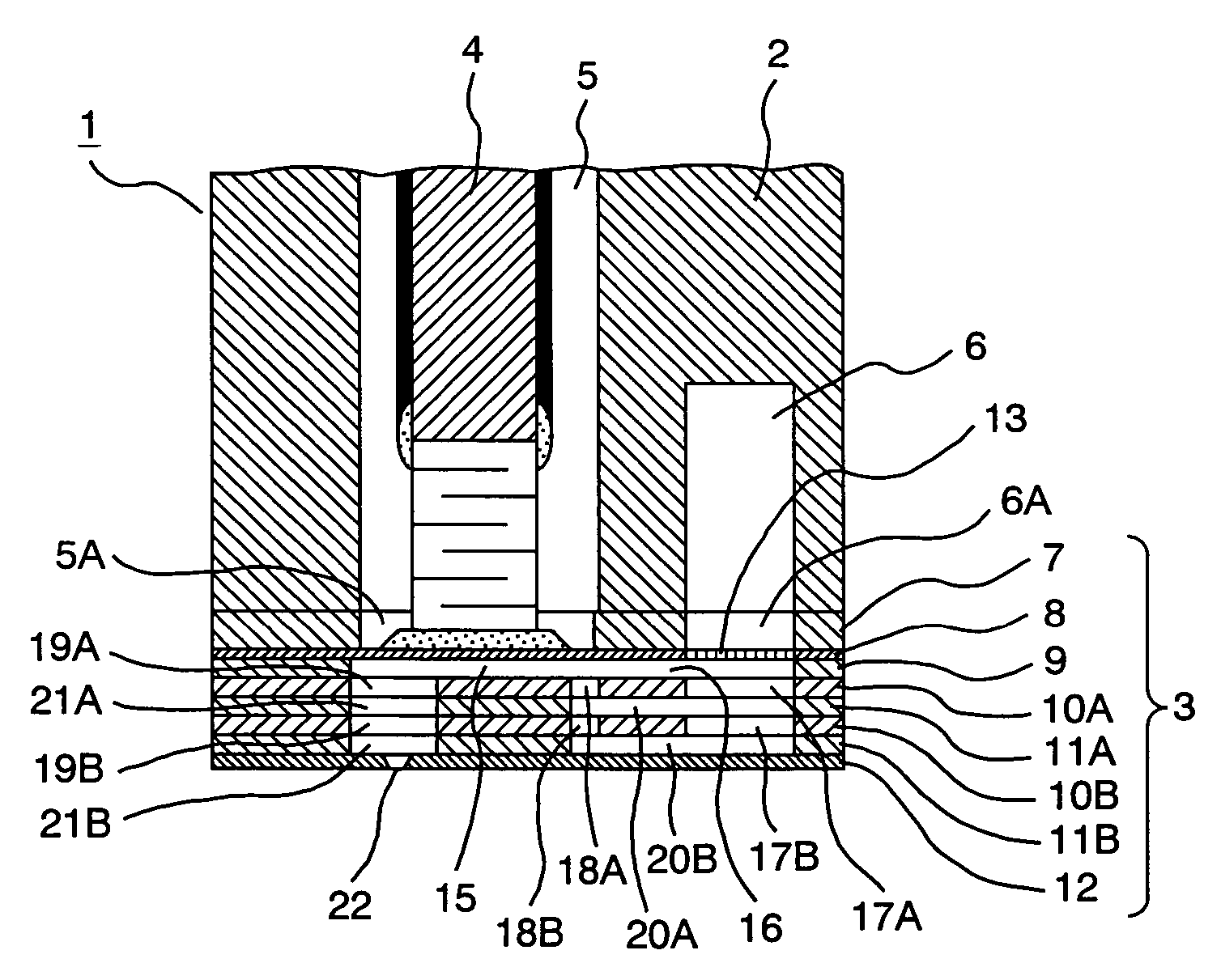
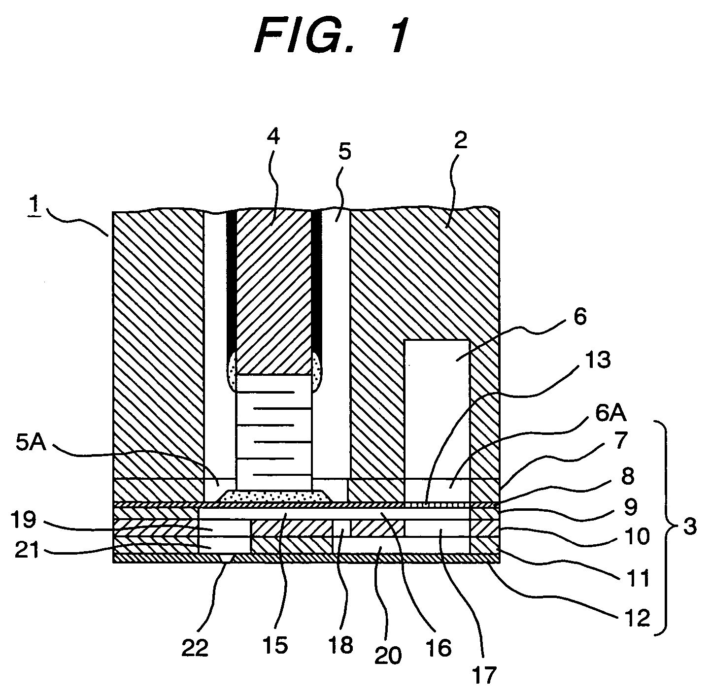
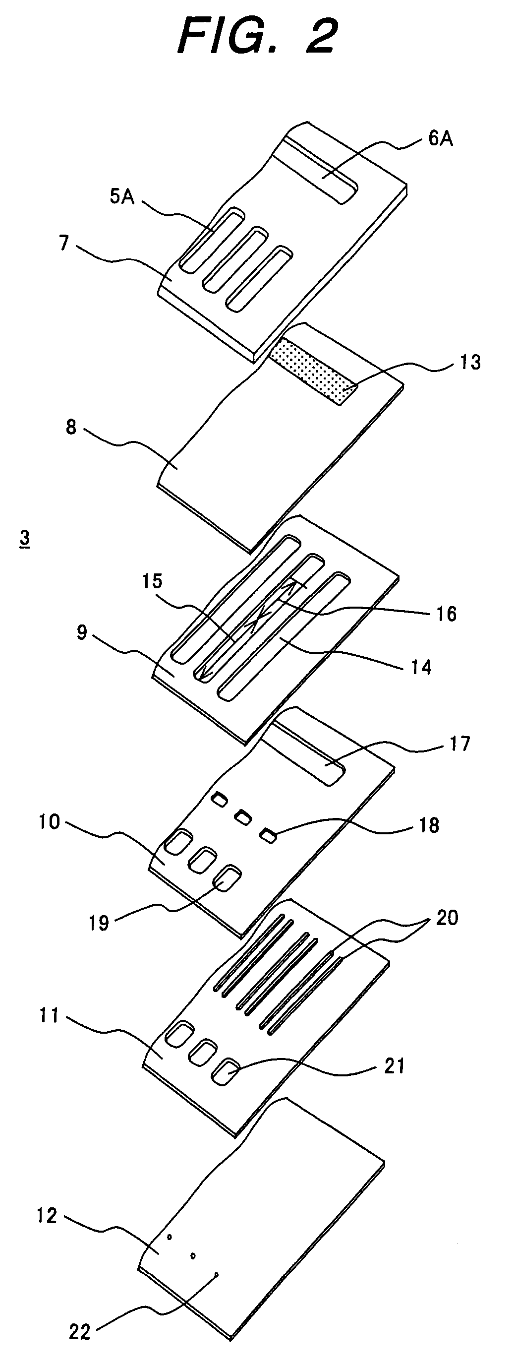
[0019]A first embodiment of an ink jet head according to the invention will be described hereinbelow on the basis of an on-demand type line-head printing apparatus shown in FIGS. 1 and 2.

[0020]An ink jet head 1 has a housing 2 as a component of the ink jet head 1, and a path plate group 3 in which an ink path is formed by stacking a plurality of thin plate members. In the housing 2, a drive chamber 5 holding a piezoelectric element group 4 is provided in the vertical direction, and a common ink chamber 6 storing an ink that is supplied from a not-shown ink supplying part is provided. The path plate group 3 is constructed by stacking and adhering a reinforcement plate 7, a diaphragm plate 8, a restrictor plate 9, chamber plates 10 and 11, and a nozzle plate 12 by adhesion or the like at the lower end of the housing 2.

[0021]The reinforcement plate 7 is provided with drive chamber holes 5A communicated with the drive chamber 5, the number of the drive chamber holes being the number as ...


PUM


Abstract

An ink jet head having: a common ink chamber for storing an ink supplied from an ink supply part; an ink supply path for supplying the ink stored in the common ink chamber; a pressure chamber to which the ink is supplied via the ink supply path; and a nozzle for discharging the ink in the pressure chamber in accordance with a pressure change in the pressure chamber. The components being constructed by stacking a plurality of thin plate members, wherein a plurality of the ink supply paths are arranged in parallel.

Description

CLAIM OF PRIORITY[0001]This application claims priority from Japanese application serial no. 2004-251677, the content of which is hereby incorporated by reference into this application.FIELD OF THE INVENTION[0002]The present invention relates to an ink jet head applied to an apparatus for printing a large sized poster, an apparatus for discharging a special solution for forming a thin film of a flat panel display, and the like.BACKGROUND OF THE INVENTION[0003]In recent years, the uses of an apparatus using an ink jet head are increasing and, concurrently, high-speed and high-quality printing is being requested. To meet the requests, it is necessary to drive an ink drop at high frequency and, to jet the ink drop at high frequency, to obtain an ink jet head having high frequency response, in other words, high ink drop jetting frequency.[0004]To increase the jetting frequency of the ink drop, the techniques disclosed in Japanese Patent Laid-Open Nos. H8(1996)-85207 and 2001-96738 have ...

Claims


Application Information

Patent Timeline
Patent Type & Authority Patents(United States)
IPC IPC(8): B41J2/045B41J2/05
CPCB41J2/14274B41J2/1612B41J2/1623
Inventor TOBITA, SATORUSUMIYA, TOSHIHARUMATSUFUJI, RYOUTA
Owner RICOH PRINTING SYST
Features
  • R&D
  • Intellectual Property
  • Life Sciences
  • Materials
  • Tech Scout
  • Unparalleled Data Quality
  • Higher Quality Content
  • 60% Fewer Hallucinations
Learn More