Liquid crystal apparatus and electronic apparatus

a technology of liquid crystal apparatus and electronic apparatus, which is applied in the direction of printed circuits, printed circuit details, instruments, etc., can solve the problems of inability to prevent the generation of electric fields between the substrate having the electrodes and the substrate not having the electrodes in the horizontal-electric-field type liquid crystal apparatus, and achieve the effect of preventing the occurrence of short circuits between the driver circuit and the tape-like conductive member

Active Publication Date: 2010-02-16
JAPAN DISPLAY WEST
View PDF14 Cites 20 Cited by
  • Summary
  • Abstract
  • Description
  • Claims
  • Application Information

AI Technical Summary

Benefits of technology

[0009]An advantage of some aspects of the invention is that a liquid crystal apparatus having a shield function for causing electric charge to pass through the liquid crystal apparatus to the outside is provided.
[0011]As described above, the liquid crystal apparatus includes a liquid crystal display panel, a conductive layer, a flexible board, and a tape-like conductive member. The liquid crystal display panel includes two substrates with liquid crystal interposed therebetween. The conductive layer is provided on the outer surface of at least one of the substrates. The flexible board is electrically connected to the liquid crystal display panel. The tape-like conductive member provides an electrical connection between the conductive layer and a grounding wire of the flexible board. With such a configuration, the liquid crystal apparatus can function as a shield against external static electricity or the like, and generation of an electric field between the substrates can be prevented.
[0012]In the liquid crystal apparatus according to the first aspect of the invention, one of the two substrates preferably has an extended portion extending beyond the other substrate, the extended portion having a surface provided thereon with a driver circuit and the flexible board. Further, the tape-like conductive member is preferably disposed across a region having the driver circuit. Furthermore, at least a region where the driver circuit and the tape-like conductive member overlap each other is preferably covered with an insulator. With such a configuration, occurrence of short circuits between the driver circuit and the tape-like conductive member can be prevented.
[0018]According to a third aspect of the invention, a method for manufacturing a liquid crystal apparatus includes fabricating a display panel in which a driver circuit and a flexible board are provided on one of two substrates in an extended portion thereof that extends beyond the other substrate, covering at least a part of the driver circuit on the extended portion with an insulator, attaching a conductive layer on an outer surface of the other substrate, and pasting one end and the other end of a tape-like conductive member to the conductive layer and a grounding wire of the flexible substrate, respectively, so as to provide an electrical connection therebetween. With this method for manufacturing a liquid crystal apparatus, occurrence of short circuits between the driver circuit and the tape-like conductive member can be prevented.

Problems solved by technology

In such a horizontal-electric-field type liquid crystal apparatus, however, if the substrate not having the electrodes is unintentionally charged with external static electricity or the like, another electric field is also generated between the substrate having the electrodes and the substrate not having the electrodes.
Consequently, proper display may not be performed.
Therefore, the generation of an electric field between the substrate having the electrodes and the substrate not having the electrodes in the horizontal-electric-field type liquid crystal apparatus cannot be prevented.

Method used


Image

  • Liquid crystal apparatus and electronic apparatus
  • Liquid crystal apparatus and electronic apparatus
  • Liquid crystal apparatus and electronic apparatus

Examples


Embodiment Construction

[0035]An embodiment of the invention will now be described with reference to the accompanying drawings. Herein, a liquid crystal apparatus according to the following embodiment of the invention incorporates an illumination device.

Configuration of Liquid Crystal Apparatus

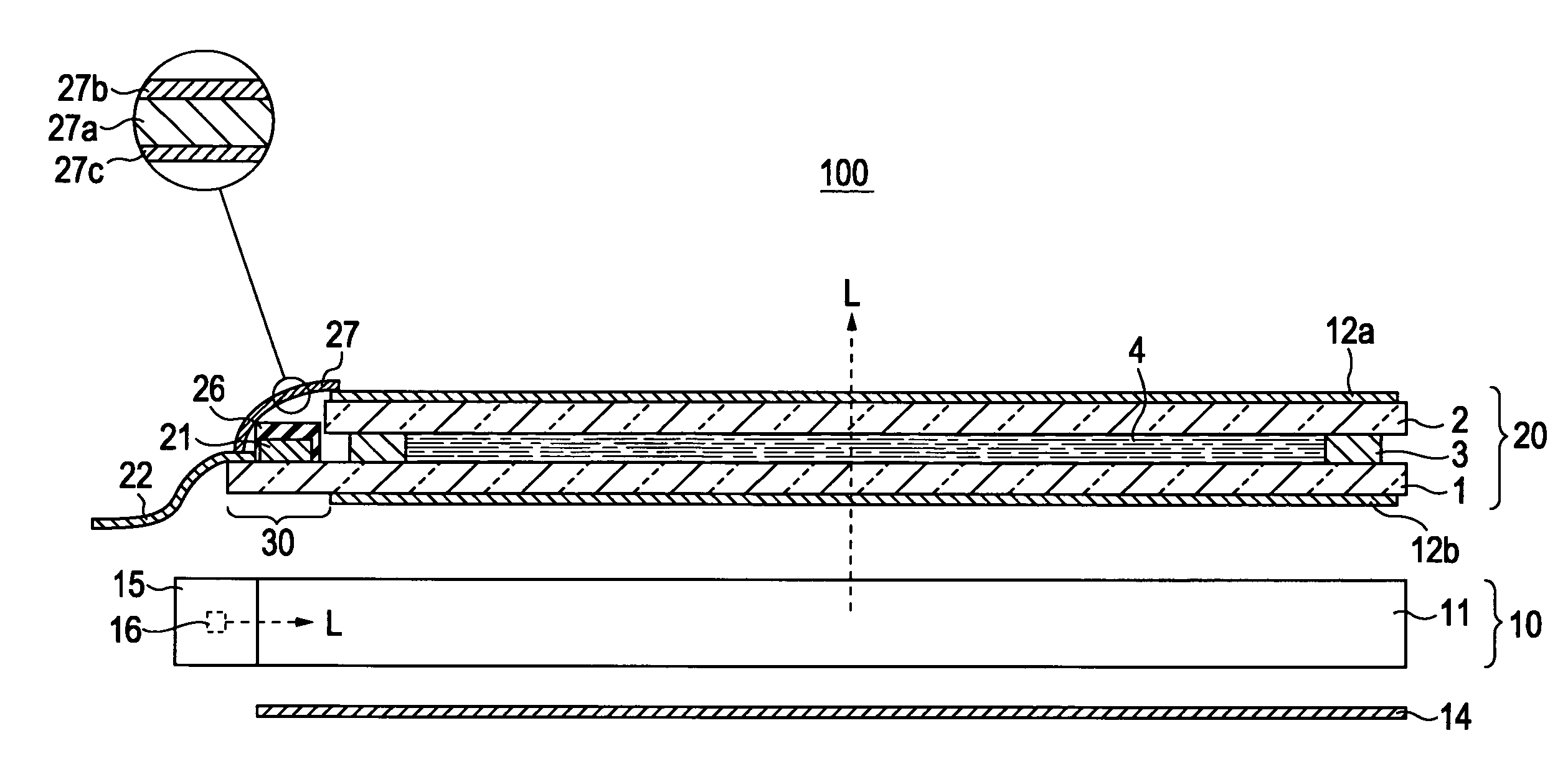
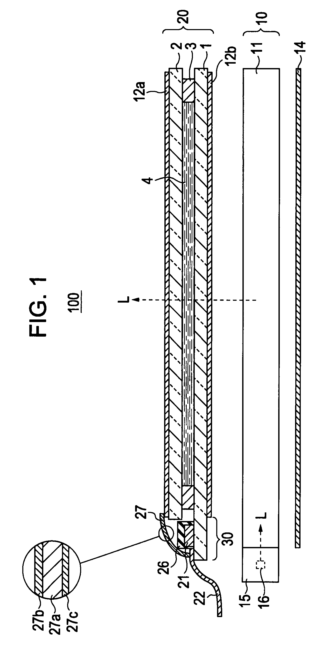
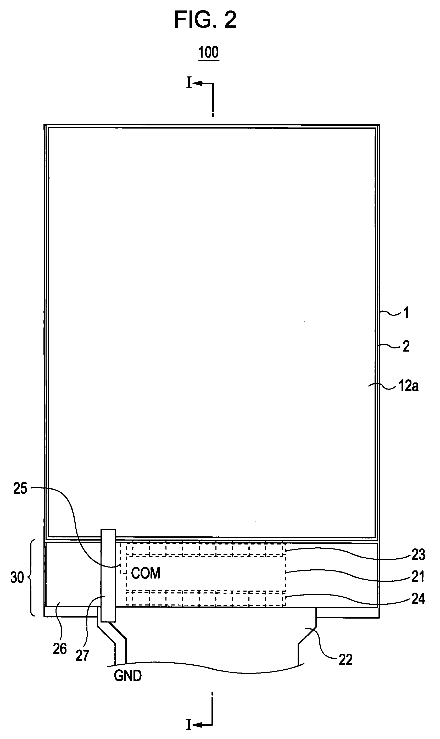
[0036]FIG. 1 is a cross-sectional view of a liquid crystal apparatus 100 according to the embodiment. FIG. 2 is a plan view of the liquid crystal apparatus 100 according to the embodiment. FIG. 1 shows a cross-section of the liquid crystal apparatus 100 in FIG. 2, taken along line I-I.

[0037]The liquid crystal apparatus 100 mainly includes an illumination device 10 and a liquid crystal display panel 20. The illumination device 10 mainly includes a light-guiding plate 11 and a light source unit 15. The liquid crystal display panel 20 is disposed above the top surface of the light-guiding plate 11. The illumination device 10 also includes a reflection sheet 14 below the bottom surface of the light-guiding plate 11.

[0038...


PUM

PropertyMeasurementUnit
flexibleaaaaaaaaaa
conductiveaaaaaaaaaa
electricalaaaaaaaaaa

Abstract

A liquid crystal apparatus includes a liquid crystal display panel including two substrates with liquid crystal interposed therebetween, a conductive layer provided on an outer surface of at least one of the substrates, a flexible board electrically connected to the liquid crystal display panel, and a tape-like conductive member providing an electrical connection between the conductive layer and a grounding wire of the flexible board.

Description

[0001]The entire disclosure of Japanese Patent Application Nos. 2006-332046, filed Dec. 8, 2006 and 2007-227828, filed Sep. 3, 2007 are expressly incorporated by reference herein.BACKGROUND[0002]1. Technical Field[0003]The present invention relates to a liquid crystal apparatus that is suitable for displaying various kinds of information.[0004]2. Related Art[0005]In recent years, liquid crystal apparatuses of a so-called horizontal-electric-field type have been attracting attention. Such apparatuses, in which an electric field applied to liquid crystal extends substantially parallel to substrates, have improved visual characteristics superior to those of the twisted-nematic (TN) type or the like. The horizontal-electric-field type liquid crystal apparatuses are further classified into apparatuses of the in-plane-switching (IPS) type, apparatuses of the fringe-field-switching (FFS) type, and the like. A horizontal-electric-field type liquid crystal apparatus includes a pair of substr...

Claims


Application Information

Patent Timeline
Patent Type & Authority Patents(United States)
IPC IPC(8): G02F1/1345
CPCG02F1/13452G02F1/133528G02F1/134363G02F2202/16H05K1/0213H05K1/147
Inventor TAKAHASHI, YOJIKIYOSE, KANECHIKA
Owner JAPAN DISPLAY WEST
Why Eureka
Try Eureka