Aluminum-halogen fuel cell

a fuel cell and halogen technology, applied in the field of fuel cells, can solve the problems of requiring a large amount of energy, requiring a large-scale apparatus, and a large amount of resistance, and achieve the effects of generating high-voltage electricity, simple solid-liquid separation operation, and reducing resistan

Active Publication Date: 2014-06-26
UEDA MIKITO +1
View PDF8 Cites 2 Cited by
  • Summary
  • Abstract
  • Description
  • Claims
  • Application Information

AI Technical Summary

Benefits of technology

[0021]The aluminum-halogen fuel cell of the present invention can be operated even at temperatures close to normal temperature, does not suffer from problems such as corrosion, suppresses any reduction in voltage caused by oxide film generation, and can generate high-voltage electricity. Further, by using the aluminum-halogen fuel cell of the

Problems solved by technology

In this cell, if the surface of the molten aluminum electrode becomes coated with an oxide film during power generation, then the resistance increases marked

Method used


Image

  • Aluminum-halogen fuel cell
  • Aluminum-halogen fuel cell
  • Aluminum-halogen fuel cell

Examples


example 1

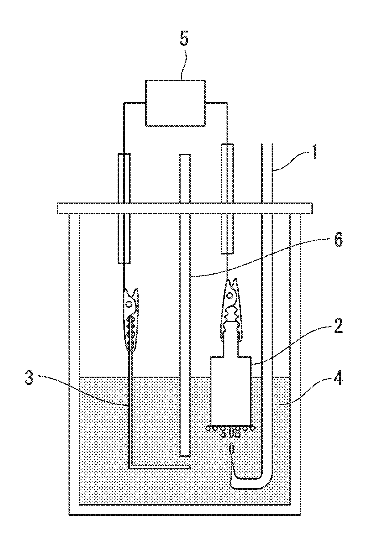
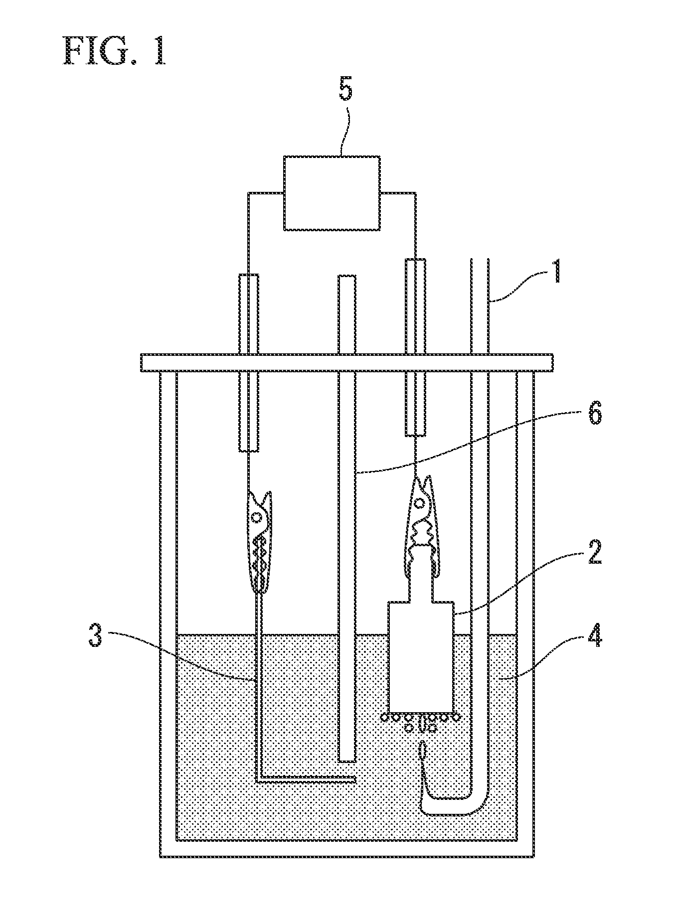
[0060]FIG. 1 illustrates a fuel cell as one embodiment of the present invention. An electrode (aluminum electrode) formed from an aluminum metal plate having a purity of 99.999% that had been polished with a No. 1000 waterproof abrasive paper was used as the negative electrode 3. For the positive electrode 2, a graphite electrode was used (formed with a circular cylindrical shape such as that illustrated in FIG. 1 having a diameter of 15 mm and a surface area of 1.77 cm2, having a contact tab provided at the top, being substantially flat on the bottom surface, and having side surfaces that had been sealed with a Teflon (registered trademark) tape). For the electrolyte 4, 150 ml of an ionic liquid obtained by mixing 1-ethyl-3-methylimidazolium chloride and aluminum chloride in a molar ratio of 2:1 was used.

[0061]In order to prevent direct contact between the chlorine gas and the aluminum electrode, a polytetrafluoroethylene separator 6 was provided. The polytetrafluoroethylene separa...

example 2

[0063]With the exception of changing the positive electrode 2 to a graphite electrode having a circular cylindrical shape with a diameter of 21 mm and a surface area of 3.46 cm2, a fuel cell was assembled with the same structure as that described in Example 1.

[0064]The temperature of the ionic liquid was set to 30° C., 40° C., or 60° C., and at each temperature, the voltage between the aluminum electrode and the graphite electrode onto which the chlorine was being bubbled was adjusted to 0.5 V, and the current density was measured. The results revealed that the current density was 9.2 mAcm−2 at 30° C., 12.2 mAcm−2 at 40° C., and 23.7 mAcm−2 at 60° C.

example 3

[0065]With the exception of changing the positive electrode 2 to a graphite electrode having a circular cylindrical shape with a diameter of 21 mm and a surface area of 4.24 cm2, a fuel cell was assembled with the same structure as that described in Example 1. The bottom surface of the electrode included three parallel V-shaped grooves such as those illustrated in FIG. 4. The width of each groove was 3.3 mm, the length from the edge of the groove to the bottom thereof was 2.5 mm, the length of the middle groove was 21 mm, and the length of each of the left and right grooves was 18 mm.

[0066]In a similar manner to Example 2, the current density at a voltage of 0.5 V was measured when the temperature of the ionic liquid was either 30° C. or 40° C. The results revealed that the current density was 11.1 mAcm−2 at 30° C. and 14.3 mAcm−2 at 40° C.


PUM


Abstract

An aluminum-halogen fuel cell has a positive electrode (2), a negative electrode (3), and an electrolyte (4) containing an ionic liquid represented by formula (1) or the like. In formula (1), R1 represents an unsubstituted or substituent-containing C1 to C20 alkyl group, R2 represents a C1 to C4 alkyl group or the like, each of R3 and R4 independently represents a hydrogen atom or the like, X represents AlCl4 or the like, and Y represents Al2Cl7 or the like.

Description

TECHNICAL FIELD[0001]The present invention relates to a fuel cell (hereafter referred to as an aluminum-halogen fuel cell) which extracts the energy generated when aluminum is halogenated as electrical power.[0002]Priority is claimed on Japanese Patent Application No. 2011-159583, filed Jul. 21, 2011, and Japanese Patent Application No. 2012-020362, filed Feb. 1, 2012, the contents of which are incorporated herein by reference.BACKGROUND ART[0003]The theoretical energy density of aluminum per unit volume is 8,050 Ah / l, which is equivalent to approximately 4 times that of lithium. Accordingly, if aluminum or an aluminum alloy can be used as the negative electrode of a cell, then a cell having a high energy density can be realized at low cost. Further, because the electrode potential of aluminum is −1.66 V (vs. the standard hydrogen electrode), indicating lower potential, by combining aluminum with an appropriate positive electrode active material, there is a possibility of achieving ...

Claims


Application Information

Patent Timeline
IPC IPC(8): H01M12/08
CPCC25B1/24C25B5/00H01M8/144H01M2300/0057H01M10/399H01M2300/0045Y02E60/50H01M12/08H01M4/9041H01M8/02H01M8/04201H01M14/00H01M2300/0025
Inventor UEDA, MIKITO
Owner UEDA MIKITO
Why Eureka
Try Eureka