Driving circuit for organic light emitting diode, display device using the same and driving method of organic light emitting diode display device

a technology of organic light emitting diodes and driving circuits, which is applied in static indicating devices, instruments, electroluminescent light sources, etc., can solve the problems of further affecting the reliability of the entire oled display devi

Active Publication Date: 2006-12-21
LG DISPLAY CO LTD
View PDF4 Cites 171 Cited by
  • Summary
  • Abstract
  • Description
  • Claims
  • Application Information

AI Technical Summary

Benefits of technology

[0013] By way of example only, in one embodiment, an organic light emitting diode drive circuit includes an organic light emitting diode which emits light by a current, a first switch to supply a data voltage to a first node in response to a scan pulse, a second switch to control a current flowing in the organic light emitting diode by the data voltage on the first node, and a stress compensation circuit to discharge the first node in response to a reset pulse. The stress compensation circuit may include a third switch. The data voltage rises from a first low potential reference voltage, and the scan pulse and the reset pulse rise from a second low potential reference voltage. The second low potential reference voltage may be lower than the first low potential reference voltage. In the organic light emitting diode drive circuit, generation of the reset pulse may be delayed by a designated time, for example, ½ frame period from generation of the scan pulse. The first to third switches may include a transistor.

Problems solved by technology

Reliability of the entire OLED display device may be further affected.

Method used


Image

  • Driving circuit for organic light emitting diode, display device using the same and driving method of organic light emitting diode display device
  • Driving circuit for organic light emitting diode, display device using the same and driving method of organic light emitting diode display device
  • Driving circuit for organic light emitting diode, display device using the same and driving method of organic light emitting diode display device

Examples


Embodiment Construction

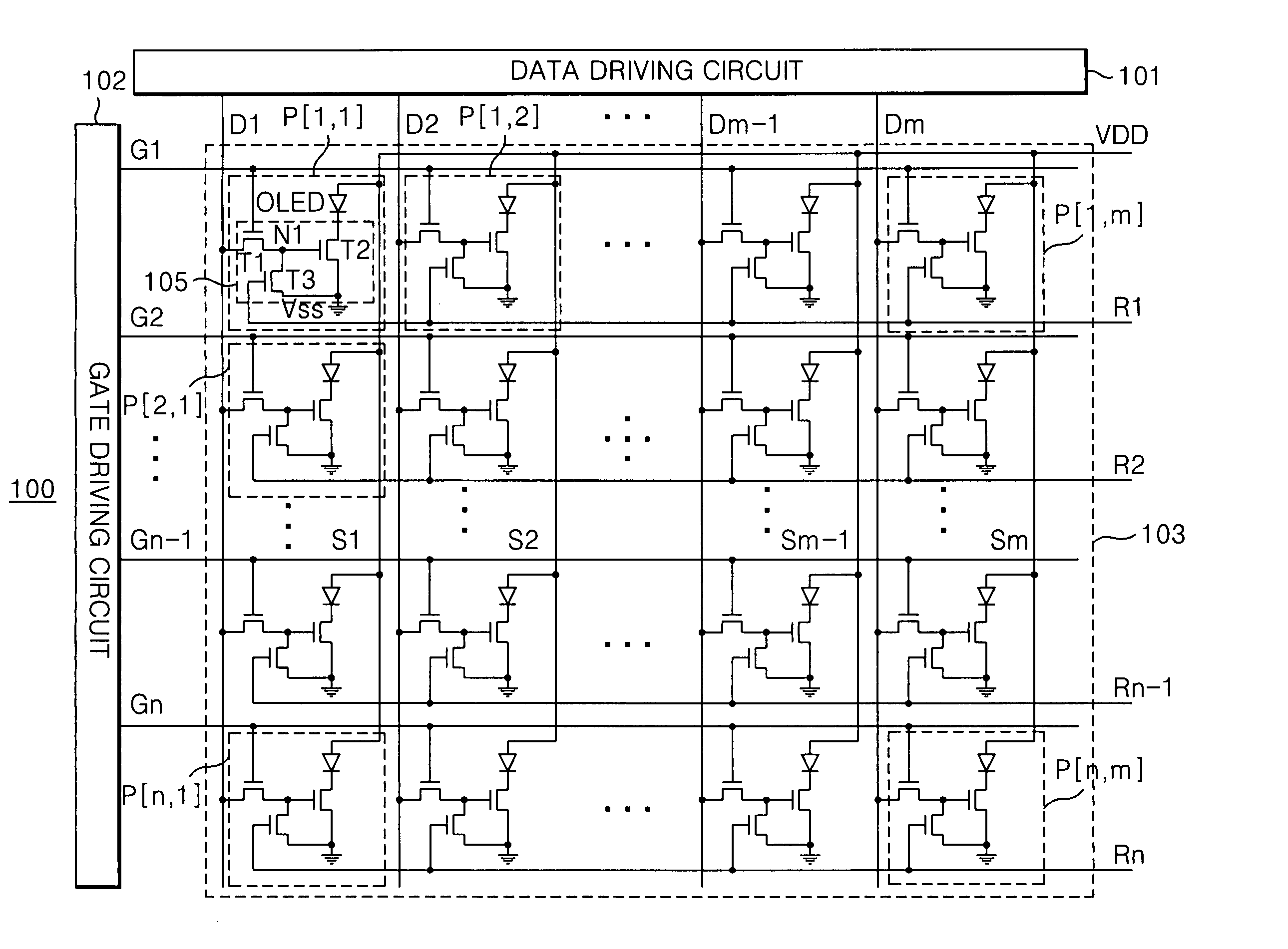
[0032]FIG. 5 illustrates one embodiment of an OLED display device 100 that includes an OLED panel 103 having n×m number of pixels P[i,j]. The pixels P[l, j] are arranged in n×m matrix at an area which is defined by n numbers of gate lines G1 to Gn and m numbers of data lines D1 to Dm. A gate drive circuit 102 drives the gate lines G1 to Gn of the OLED panel 103, and a data drive circuit 101 drives the data lines D1 to Dm of the OLED panel 103. The m number of power voltage supply lines S1 to Sm are arranged in parallel to the data lines D1 to Dm to supply the high potential power voltage Vdd to each pixel P[i,j]. In the OLED display device 100, reset lines R1 to Rn are arranged in parallel to the gate lines G1 to Gn to supply a reset signal to each pixel P[i,j].

[0033] The gate drive circuit 102 supplies scan pulses to the gate lines G1 to Gn to sequentially drive the gate lines G1 to Gn. The data drive circuit 101 converts a digital data voltage input from the outside into an analo...


PUM


Abstract

An organic light emitting diode drive circuit includes an organic light emitting diode which emits light with a current, a first transistor, a second transistor and a stress compensation circuit. The first transistor supplies a data voltage to a first node in response to a scan pulse. The second transistor controls a current flowing in the organic light emitting diode by the data voltage on the first node. The stress compensation circuit discharges the first node in response to a reset pulse. The organic light emitting diode driving circuit is adaptive to compensate characteristic changes of the organic light emitting diode drive circuit.

Description

[0001] This application claims the benefit of the Korean Patent Application No. P2005-53120 filed on Jun. 20, 2005, which is hereby incorporated by reference in its entirety. BACKGROUND [0002] 1. Technical Field [0003] The present invention relates to an organic light emitting diode display device, and more particularly to an organic light emitting diode driving circuit with minimized characteristic changes. [0004] 2 Related Art [0005] Various flat panel display devices gradually replace a cathode ray tube (CRT) because they may be compact, light and thin. Flat panel display devices include a liquid crystal display (LCD), a field emission display (FED), a plasma display panel (PDP), a light emitting diode (LED) display device and so on. [0006] An LED display device uses an LED which emits light by recombining electrons and holes. The LED display device is divided into an inorganic LED display device which uses inorganic compounds and an organic light emitting diode (OLED) display de...

Claims


Application Information

Patent Timeline
Patent Type & Authority Applications(United States)
IPC IPC(8): G09G3/30H05B44/00
CPCG09G3/3233G09G3/3291G09G2320/043G09G2300/0847G09G2310/0254G09G2300/043G09G3/30
Inventor YOON, SOO YOUNGCHUN, MIN DOO
Owner LG DISPLAY CO LTD
Why Eureka
Try Eureka