Device for transporting liquid and system for analyzing

a liquid transport device and liquid technology, applied in the field of liquid manipulating systems, can solve the problems of time and effort, inability to accurately measure, and difficulty in handling liquid, and achieve the effects of simple mounting, stable and independent manipulation, and throughput of the system for analyzing

Inactive Publication Date: 2006-11-16
HITACHI HIGH-TECH CORP
View PDF9 Cites 177 Cited by
  • Summary
  • Abstract
  • Description
  • Claims
  • Application Information

AI Technical Summary

Benefits of technology

[0016] According to the present invention, the mounting is simpler as compared with the conventional device for transporting liquid which is filled with oil, and a stable and independent manipulation can be carried out to a plurality of liquids, and the liquid will not move out of control due to an oil flow generated by the manipulations of liquid, such as dispensing, transporting, or the like. Moreover, the liquid enclosed by a fractionated oil droplet can be introduced sequentially into the device for transporting liquid, and the throughput of the system for analyzing which treats a plurality of samples can be increased.

Problems solved by technology

However, recently, for the purpose of reduction in the reagent cost and in the environmental load, there is a need for minimalizing the amount of reaction liquids used for analysis, and with the conventional scheme for minimalizing the amount of reaction liquids, the handling of liquid becomes difficult, and the scheme also has a problem that accurate measurements can not be made due to air bubbles generated during the dispensing and mixing.
However, because the bottom face and side face of the device for transporting liquid need to be sealed such that the oil will not leak therethrough, it takes time and efforts to mount.
Moreover, a problem can be conceived in that when manipulating liquid, a flow occurs in oil, thereby giving affect to other liquids.
For example, problems can be conceived in: that when introducing liquid into the device for transporting liquid, a probe for dispensing liquid, and the introduced granular liquids generate a flow in the oil, thereby moving another liquid arranged in the device for transporting liquid: and the like.
In the case where liquid moves out of control, it is very likely that the liquid come in contact with other liquids to mix, or that the liquid moves away from a liquid-transporting passage, and thus the transporting may not be possible.
Moreover, considering an application to a system for analyzing wherein the measurement is carried out in the device for transporting liquid, a problem can be conceived in that if air bubbles come into oil from a liquid introducing port, the air bubbles will prevent the measurement in the measurement section, and so on.
However, unlike the case where the liquid is enclosed by oil, the liquid is in contact directly with the surface of the device for transporting liquid, therefore, problems can be conceived in that the ingredient inside the liquid will likely adsorb; that the voltage required for moving is high because the friction between the liquid and the device for transporting liquid is high; that the evaporation of the liquid cannot be prevented; and the like.

Method used


Image

  • Device for transporting liquid and system for analyzing
  • Device for transporting liquid and system for analyzing
  • Device for transporting liquid and system for analyzing

Examples


embodiment 1

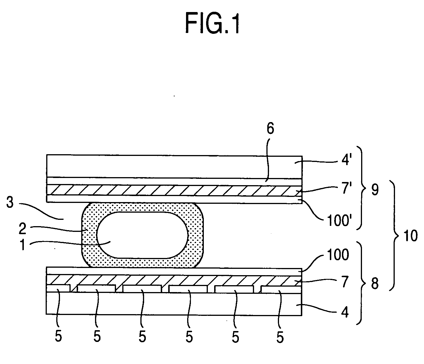
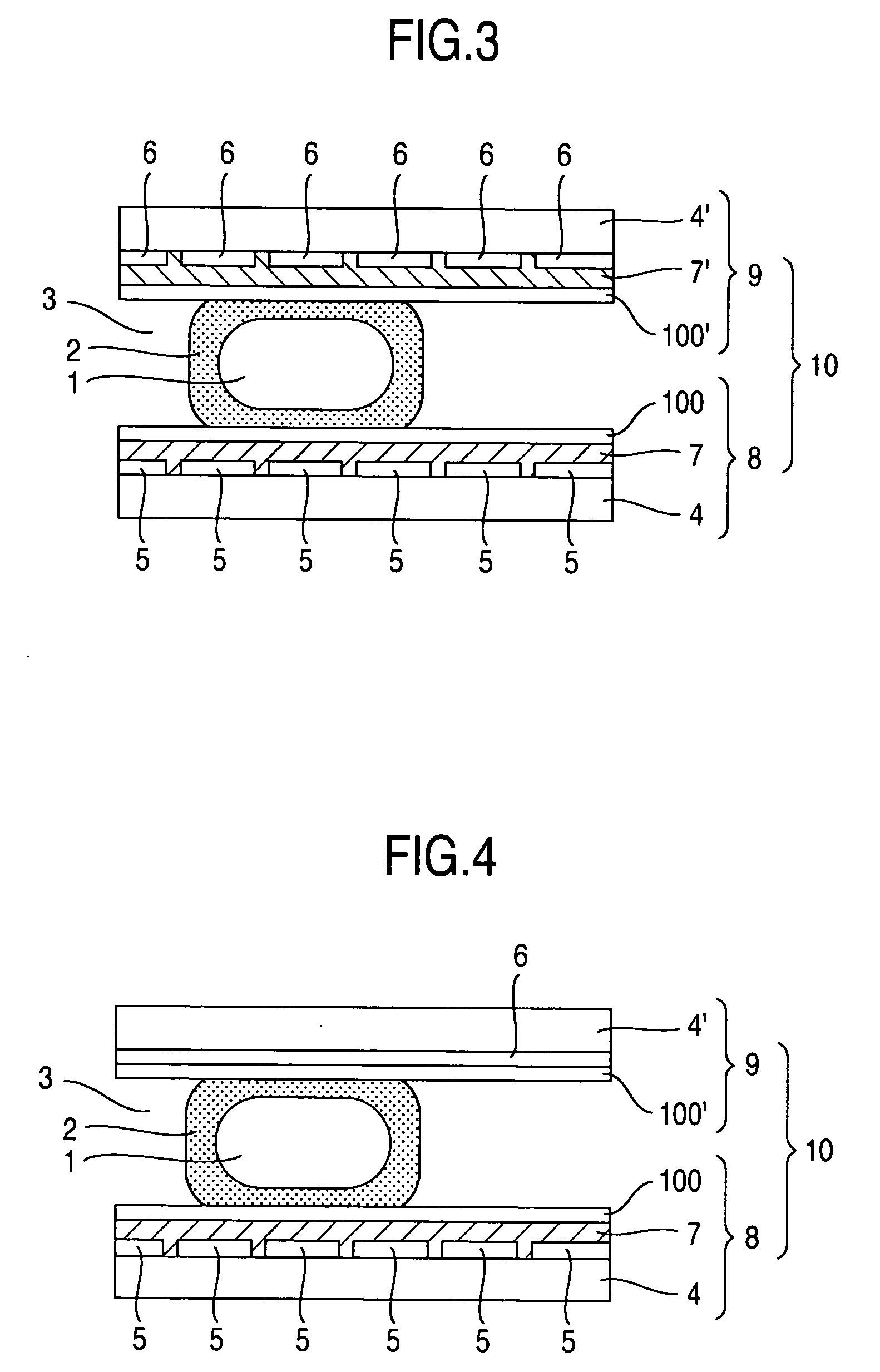
[0076] This example shows a procedure, wherein an oil droplet is used as a droplet for liquid used for transporting in a device for transporting liquid to thereby transport the liquid enclosed by the oil droplet. FIG. 1 shows a cross sectional configuration in a liquid-transporting passage of a device for transporting liquid 10 in this example. The device for transporting liquid 10 comprises a lower substrate 8 and an upper substrate 9. In the lower substrate 8, multiple control electrodes 5 are arranged along the transporting direction of a liquid (droplet) 1 in the upper surface of an insulating substrate 4, and moreover the surface thereof is covered with an insulating film 7. In the upper substrate 9, one common electrode 6 is arranged in the lower surface of an insulating substrate 4′, and the surface thereof is covered with an insulating film 7′. Furthermore, in the surfaces of the respective insulating films 7 and 7′, water-repellent films 100, 100′ are applied to the surface...

embodiment 2

[0087] This example shows a procedure wherein mixing or the like of two liquids enclosed by the oil droplet 2 is carries out. The mixing procedure is divided into combining and stirring to be described hereinafter. When a liquid (droplet) la enclosed by an oil droplet 2a and a liquid 1b enclosed by an oil droplet 2b are placed on the control electrode 5 as shown in FIG. 9A, if a voltage is applied to control electrodes 5b and 5d which are located in between the two liquids (droplets), and on which a part of the respective droplets overlap, respectively, the liquids (droplets) 1a and 1b will move as to rest upon the control electrode which the respective part thereof overlapped, as shown in FIG. 9B. Then, a voltage is applied to a control electrode 5c, which is the control electrode arranged in between the two liquids (droplets) as shown in FIG. 9C, the control electrode 5c being arranged in between the control electrodes 5b and 5d, the control electrode 5c being the destination of t...

embodiment 3

[0090] This example shows a procedure for separating one liquid 1 enclosed by the oil droplet 2 into two liquids 1 enclosed by the oil droplet 2.

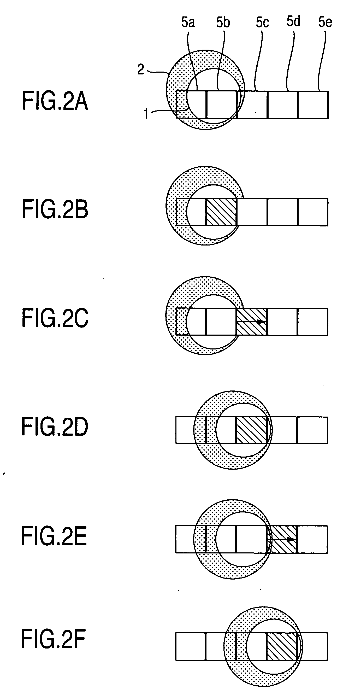
[0091] When the liquid 1 enclosed by the oil droplet 2 is placed on the control electrode 5 arranged in a straight line, as shown in FIG. 13A, a voltage is applied simultaneously or substantially simultaneously to the control electrode 5c, which a part of the liquid 1 overlaps and which is also located near the center of the liquid 1, and to the control electrodes 5b and 5d, which are adjacent to the control electrode located near the center of the liquid and are in a symmetrical position relative to the control electrode concerned as shown in FIG. 13B. Then, as shown in FIG. 13C, the liquid will deform wide horizontally. Then, the applied voltage to the control electrode 5c located near the center of the liquid is turned off. This separates the liquid 1 into two liquids (droplets) 1a and 1b, as shown in FIG. 13D. At this time, a voltage i...


PUM

PropertyMeasurementUnit
thicknessaaaaaaaaaa
thicknessaaaaaaaaaa
distanceaaaaaaaaaa

Abstract

In a device for transporting liquid, liquid to be transported is enclosed by an oil droplet, which is fractionated with air, for manipulation. Moreover, as a method for supplying liquids wherein a plurality of liquids are enclosed by an oil droplet sequentially and treated, liquid enclosed by an oil droplet is formed by associating one oil with one liquid in a liquid introducing section. According to the present invention, even in the case where a plurality of liquids are manipulated, it is possible to manipulate stably without affecting other liquids. Moreover, it is possible to treat as a liquid enclosed by an oil droplet successively in the device for transporting liquid, thereby allowing the invention to be applied to a system for analyzing easily.

Description

INCORPORATION BY REFERENCE [0001] The present application claims priority from Japanese application JP2005-140581 filed on May 13, 2005, the content of which is hereby incorporated by reference into this application. BACKGROUND OF THE INVENTION [0002] The present invention relates to systems for manipulating liquid on a substrate, and especially to systems for analysis or reaction wherein multiple liquids are transported. [0003] As an analyzer for detecting the amount of ingredient contained in a sample, a spectral analyzer is widely used, wherein a white light from a halogen lamp or the like is irradiated at a reaction liquid, which is a mixed solution of a sample and a reagent, and then a light having transmitted through the reaction liquid is dispersed by means of a diffraction grating to extract a necessary wavelength component and determine its absorbancy, thereby measuring the amount of a desired ingredient. Alternatively, a white light may be irradiated at a reaction liquid a...

Claims


Application Information

Patent Timeline
Patent Type & Authority Applications(United States)
IPC IPC(8): G01F1/64G01N17/04
CPCG01N35/08Y10T436/2575G02B26/004
Inventor ADACHI, SAKUICHIROHARADA, KUNIOENOKI, HIDEOYAMAZAKI, ISAO
Owner HITACHI HIGH-TECH CORP
Why Eureka
Try Eureka