Kink-resistant bifurcated prosthesis

a bifurcated prosthesis and kink-resistant technology, applied in the field of implants, can solve the problems of high incidence of repeat intervention, long patient recovery time, morbidity and mortality, etc., and achieve the effects of reducing the delivery profile, enhancing the device's kink resistance, and reducing the risk of infection

Inactive Publication Date: 2010-03-23
WL GORE & ASSOC INC
View PDF477 Cites 107 Cited by
  • Summary
  • Abstract
  • Description
  • Claims
  • Application Information

AI Technical Summary

Benefits of technology

[0027]In another embodiment an inventive stent-graft construction may provide for at least two segments of the stent-graft to have different structural properties from each other. The structural properties may include flexibility and axial stiffness. With such a construction, it is possible to optimize the performance characteristics for ideal delivery and at the same time enhance the device's kink resistance, its ability to maintain its deployed position, and its conformability (which is helpful to effectuate required sealing against the vessel wall). In a preferred embodiment, the axial stiffness is varied according to the presence or absence of extended strut features or the use of a tape member of varying thickness or width.
[0028]According to another embodiment of the present invention, the bifurcated stent-graft may be constructed to have a region of single lumen stent covering a

Problems solved by technology

Shortcomings of this invasive procedure include the morbidity and mortality associated with major surgery, long patient recovery times, and the high incidence of repeat intervention needed due to limitations of the graft or of the procedure.
When a defect, such as an aneurysm, is located very close to the bifurcation of a trunk lumen into two branch lumens, treatment becomes especially difficult.
As we shall see, deployment of implants adapted to meet these needs is also problematic in that they must be deployed and secured in three different lumen which are impossible to access from a single direction.
A number of bifurcated graft implants have been developed which use some limited means of supporting the one-piece bifurcated graft structure.
As with all such one-piece devices, the delivery of the graft implant is complicated by the fact that each of the trunk and two legs of the graft must be positioned in

Method used


Image

  • Kink-resistant bifurcated prosthesis
  • Kink-resistant bifurcated prosthesis
  • Kink-resistant bifurcated prosthesis

Examples


Embodiment Construction

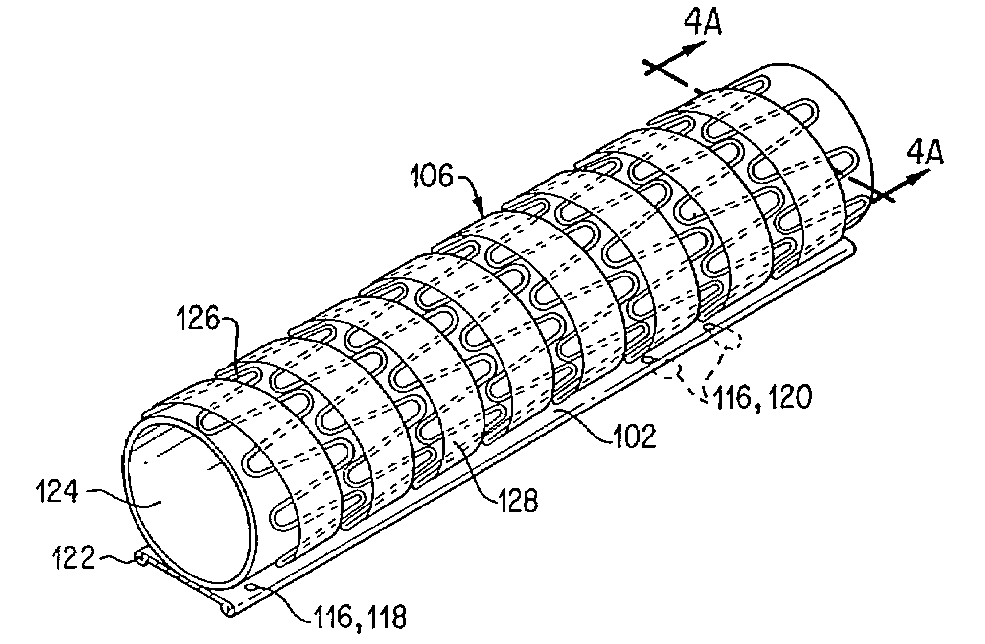
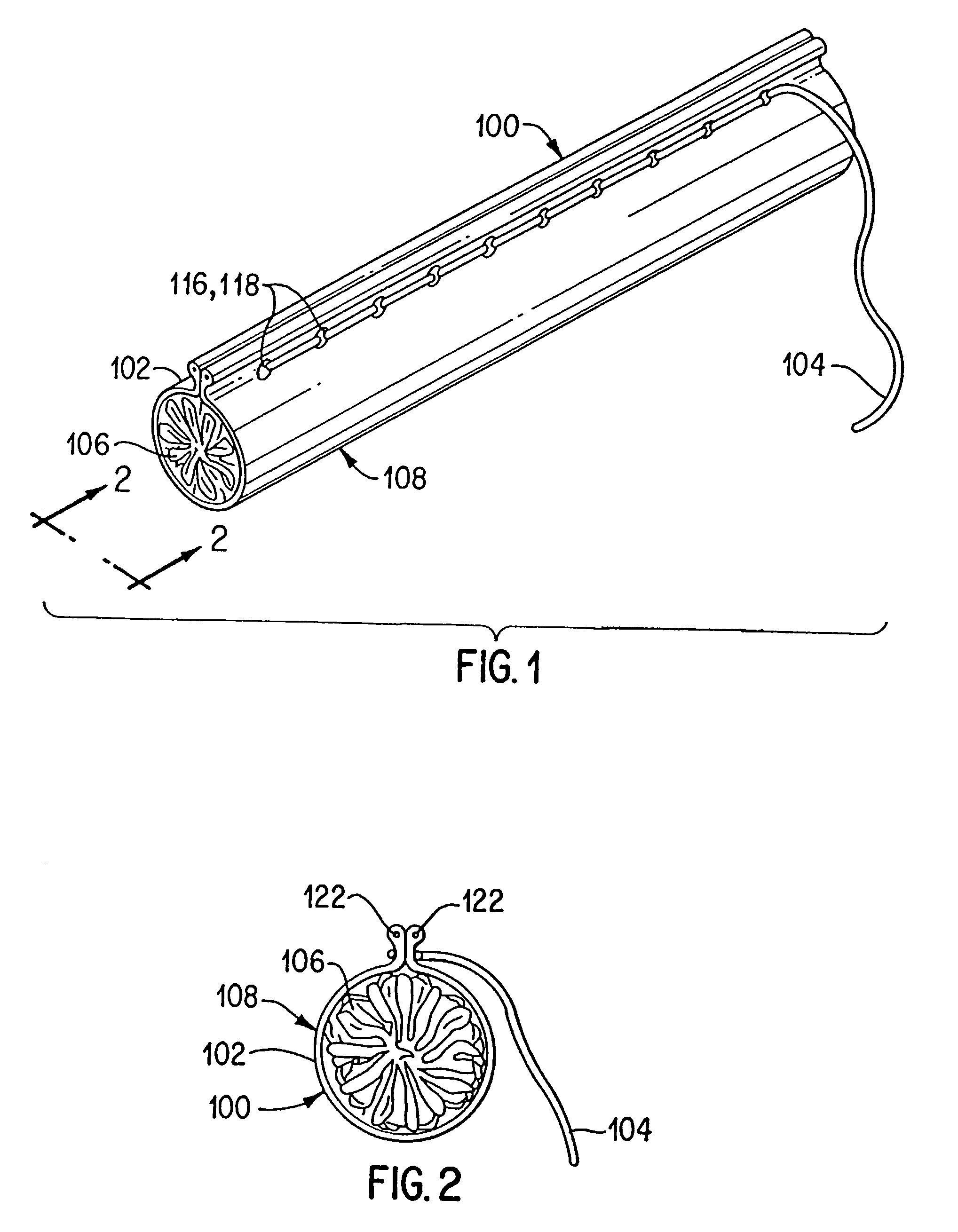
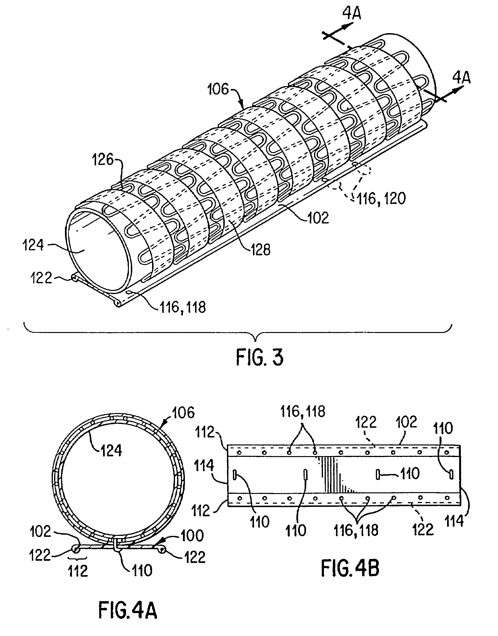
[0077]The following disclosure relating to the present invention will use certain nomenclature as set forth below. The term distal, as hereinafter used, is meant to refer to locations that are furthest away from the catheter delivery hub. Proximal is meant to refer to locations that are closer to the catheter delivery hub.

[0078]Referring to the drawings in detail wherein like numerals indicate like elements, the present invention generally involves bifurcated implants such as stents or stent-grafts for delivery to a desired site through a body's vasculature. This may involve delivery systems that can be used in conjunction with such implants. As this invention is a involves both bifurcated components as well as non-bifurcated components, it is worthwhile to begin by describing in detail the general prosthesis construction and preferred manner of deployment that is applicable to both straight and bifurcated stents or stent-grafts in accordance with FIGS. 1-13. The bifurcated prosthes...


PUM


Abstract

The invention consists of an endoluminal prosthesis adapted for placement at a bifurcation site within the body. The stent or stent-graft may be constructed to have segments of differing structural properties. A section of the stent-graft may be constructed to have a single-lumen tubular stent member covering a multilumen graft member. The stent-graft may comprise at least two modular components adapted for in situ assembly. An extended cylindrical interference fit may be used to seal the modular components.

Description

[0001]This is a continuation application under 37 C.F.R. §1.53(b) of U.S. application Ser. No. 08 / 772,372, flied Dec. 23, 1996, now U.S. Pat. No. 6,551,350, issued on Apr. 22, 2003, which is incorporated herein by reference in its entirety.TECHNICAL FIELD[0002]This invention relates generally to implants for repairing ducts and passageways in a body. More specifically this invention relates to an implant adapted for delivery to and repair of a bifurcation site within the body. In one aspect, this invention involves a modular, kink-resistant, bifurcated stent-graft device.BACKGROUND ART[0003]Treatment or isolation of vascular aneurysms or of vessel walls which have been thickened by disease has traditionally been performed via surgical bypassing with vascular grafts. Shortcomings of this invasive procedure include the morbidity and mortality associated with major surgery, long patient recovery times, and the high incidence of repeat intervention needed due to limitations of the graft...

Claims


Application Information

Patent Timeline
IPC IPC(8): A61F2/06A61F2/915A61F2/07
CPCA61F2/06A61F2/07A61F2002/067A61F2002/075A61F2002/9586A61F2250/0039A61F2/89A61F2/91A61F2250/0098
Inventor THORNTON, TROYCHAN, RANDY S.LAU, LILIP
Owner WL GORE & ASSOC INC
Why Eureka
Try Eureka