Embolic filter device and method of manufacturing the same

a filter device and filter body technology, applied in the field of embolism filter devices, can solve the problems of stenosis, narrowing of the vascular channel, restricted blood flow, serious health risks of people, etc., and achieve the effects of reducing the delivery profile, facilitating the placement of patients inside the vasculature, and simplifying the manufacturing process

Inactive Publication Date: 2009-05-28
SALVIAC
View PDF7 Cites 0 Cited by
  • Summary
  • Abstract
  • Description
  • Claims
  • Application Information

AI Technical Summary

Benefits of technology

[0011]An object of the present invention is to provide an embolic filter device having a reduced delivery profile.
[0012]Another object of the present invention is to provide an embolic filter device having a simplified manufacturing process.
[0013]Yet another object of the invention is to provide an embolic filter device which is easier to locate inside the vasculature of a patient.
[0014]According to an aspect of the present invention, there is provided a method of manufacturing an embolic filter device, the method including reducing a wall thickness of a tube in a central region between a proximal end portion and a distal end portion of the tube; cutting the proximal end portion of the tube to form an annular ring at a proximal end of the proximal end portion; cutting a plurality of slits in the central region; and expanding a portion of the tube between the annular ring and the distal end portion.

Problems solved by technology

Localized accumulation of deposits within regions of the blood vessels may result in stenosis, or narrowing of the vascular channel.
When this occurs, blood flow is restricted and the person's health is at serious risk.
Related art filter elements, such as, for example, those described above, suffer from a number of problems.
This process increases the number of steps and complexity of the manufacturing process required to produce the overall device assembly.
Third, the filter media of the related art filter element is not radio-opaque, making the filter element more difficult to locate when the filter element is inside the vasculature of a patient, thus increasing the complexity of the treatment procedure and increasing the potential for causing treatment errors.

Method used


Image

  • Embolic filter device and method of manufacturing the same
  • Embolic filter device and method of manufacturing the same
  • Embolic filter device and method of manufacturing the same

Examples


Embodiment Construction

[0022]Hereinafter, exemplary embodiments of the present inventive concept will be described in detail with reference to the drawings. The same reference numbers are used to denote the same elements even in different drawings.

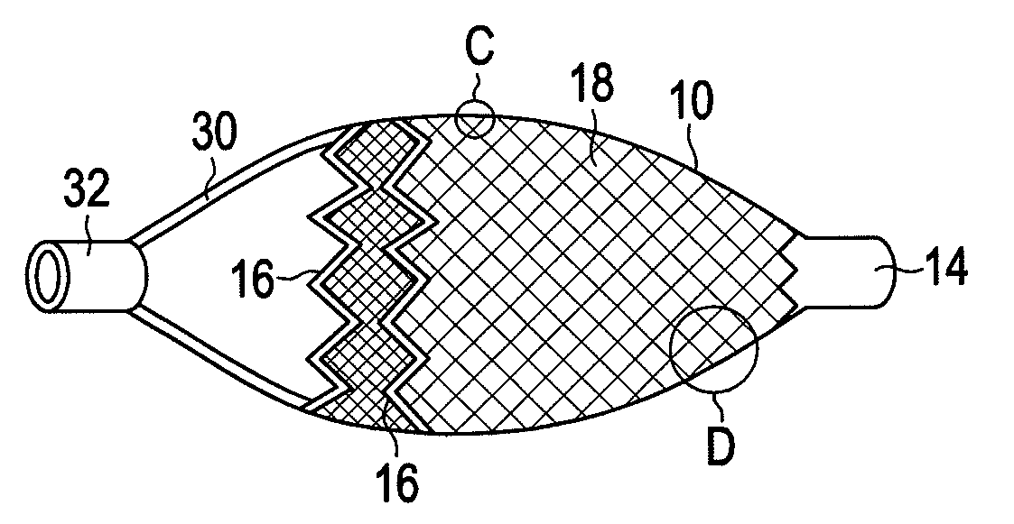
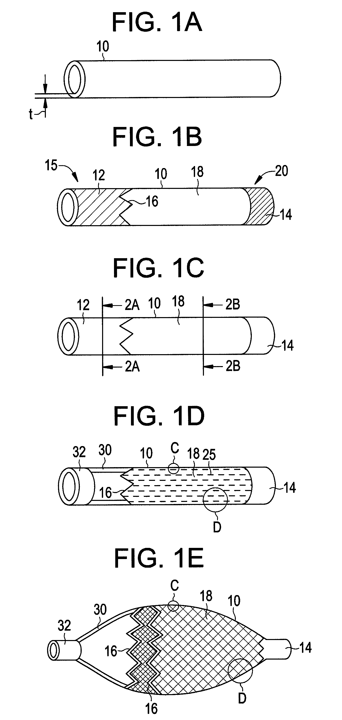
[0023]Referring to FIGS. 1A to 1E, a method of manufacturing an embolic protection filter according to an exemplary embodiment of the present invention is shown. The method begins in FIG. 1A with a tube 10. The tube 10 is hollow and has a wall thickness t. The tube is made of nitinol or other material having physical properties similar to nitinol.

[0024]As shown in FIG. 1B, tube 10 has a proximal end 15 and a distal end 20. A proximal end portion 12 of the tube 10 and a distal end portion 14 of the tube 10 are masked to create a central region 18 which remains unmasked. The proximal end portion 12 may be masked in a pattern 16, as shown in FIG. 1B.

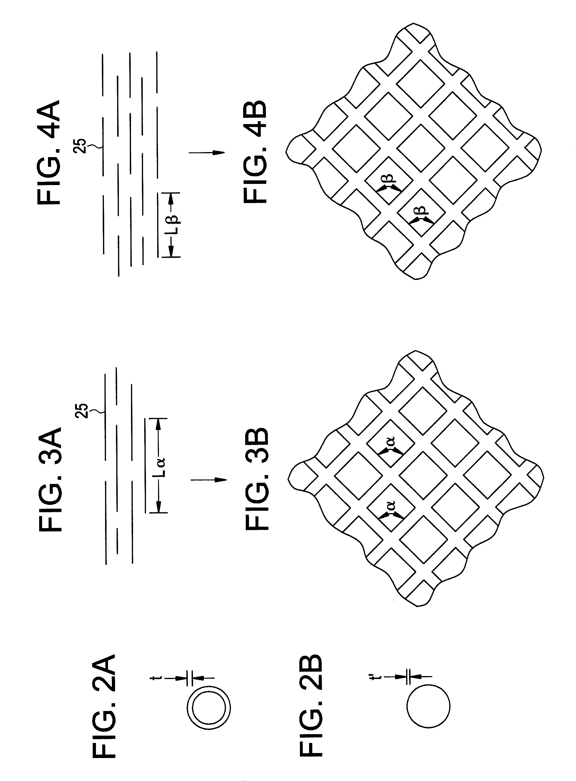
[0025]The central region 18 is then etched to reduce the wall thickness in the central region 18. FIG. 2A shows a cro...


PUM


Abstract

An embolic filter device and method of manufacturing the same are provided. The method includes reducing a wall thickness of a tube in a central region between a proximal end portion and a distal end portion of the tube; cutting the proximal end portion of the tube to form an annular ring at a proximal end of the proximal end portion; cutting a plurality of slits in the central region; and expanding a portion of the tube between the annular ring and the distal end portion. The device includes a distal annular ring; a mesh connected to the distal annular ring; and a proximal annular ring connected to the mesh by at least two connecting portions.

Description

BACKGROUND OF THE INVENTION[0001]1. Field of the Invention[0002]Devices and methods consistent with the present invention relate to filters for filtering plaque and other occlusions in blood vessels and, more particularly, to an embolic filter device formed as a single component for filtering plaque and other occlusions dislodged during treatment of stenosis in a vasculature.[0003]2. Description of the Related Art[0004]Arteriosclerosis, also known as atherosclerosis, is a common human ailment arising from the deposition of fatty-like substances, referred to as atheroma or plaque, on the walls of blood vessels. Such deposits occur in peripheral blood vessels that feed limbs of the body, coronary blood vessels that feed the heart, and in carotid blood vessels that feed the head, neck, and brain. Localized accumulation of deposits within regions of the blood vessels may result in stenosis, or narrowing of the vascular channel. When this occurs, blood flow is restricted and the person's...

Claims


Application Information

Patent Timeline
Patent Type & Authority Applications(United States)
IPC IPC(8): A61F2/06
CPCA61F2230/008A61F2/01A61F2230/0006A61F2002/018A61F2250/0023A61F2/0108
Inventor GRIFFIN, PATRICK
Owner SALVIAC
Why Eureka
Try Eureka