Branch vessel stent graft

a stent and graft technology, applied in the field of medical devices, can solve problems such as the difficulty of the design of the stent graft deployment system, and achieve the effects of reducing the system delivery profile, convenient use, and easy deploymen

Inactive Publication Date: 2015-10-13
COOK MEDICAL TECH LLC
View PDF21 Cites 4 Cited by
  • Summary
  • Abstract
  • Description
  • Claims
  • Application Information

AI Technical Summary

Benefits of technology

[0005]It is the object of this invention to provide an alternative branch vessel stent graft which will make the process of deployment of a graft into a branch vessel more straightforward or at least to provide the physician with a useful alternative.
[0019]It will be seen that by this invention the stent for the extension piece is deployed in a separate stage than the deployment of the actual graft for the side arm and therefore makes it easier to use any bare stent such as a self expanding or balloon expandable stent for the stent stage. Such a separately deployed bare stent is considerably smaller in diameter than a covered balloon expandable stent for instance and therefore can be more easily deployed using existing technologies. The graft portion of the side branch is attached securely to the main side arm stent graft and loaded as an integral part. After the stent graft is implanted a bare stent can then subsequently be deployed to keep the branch vessel graft open and attached to the vasculature.
[0020]This arrangement has two significant advantages. First of all there can be a lower system delivery profile for the stent for the side arm.
[0021]A second advantage is that affective sealing can be obtained because the extension piece for the side arm is effectively sealed to the extension piece during manufacture of the stent graft.

Problems solved by technology

The limitation of a delivery system for such balloon expandable covered stents is normally 7 to 8 French which makes the design of the stent graft deployment system challenging.
A further challenge is then providing a sufficient attachment between the branch vessel stent graft and the side arm of the main graft since endoleaks can occur and these are of significant concern.

Method used


Image

  • Branch vessel stent graft
  • Branch vessel stent graft
  • Branch vessel stent graft

Examples


Embodiment Construction

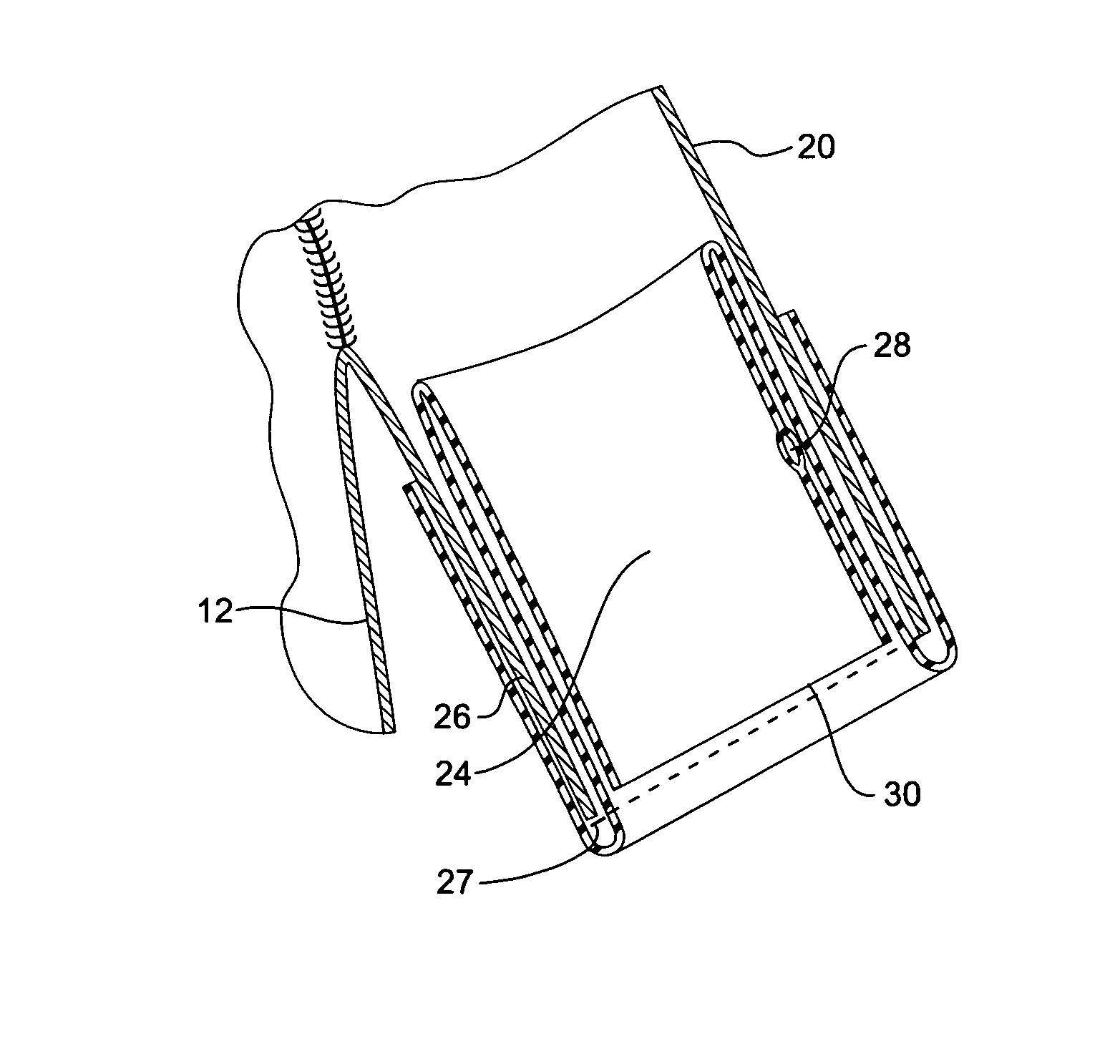
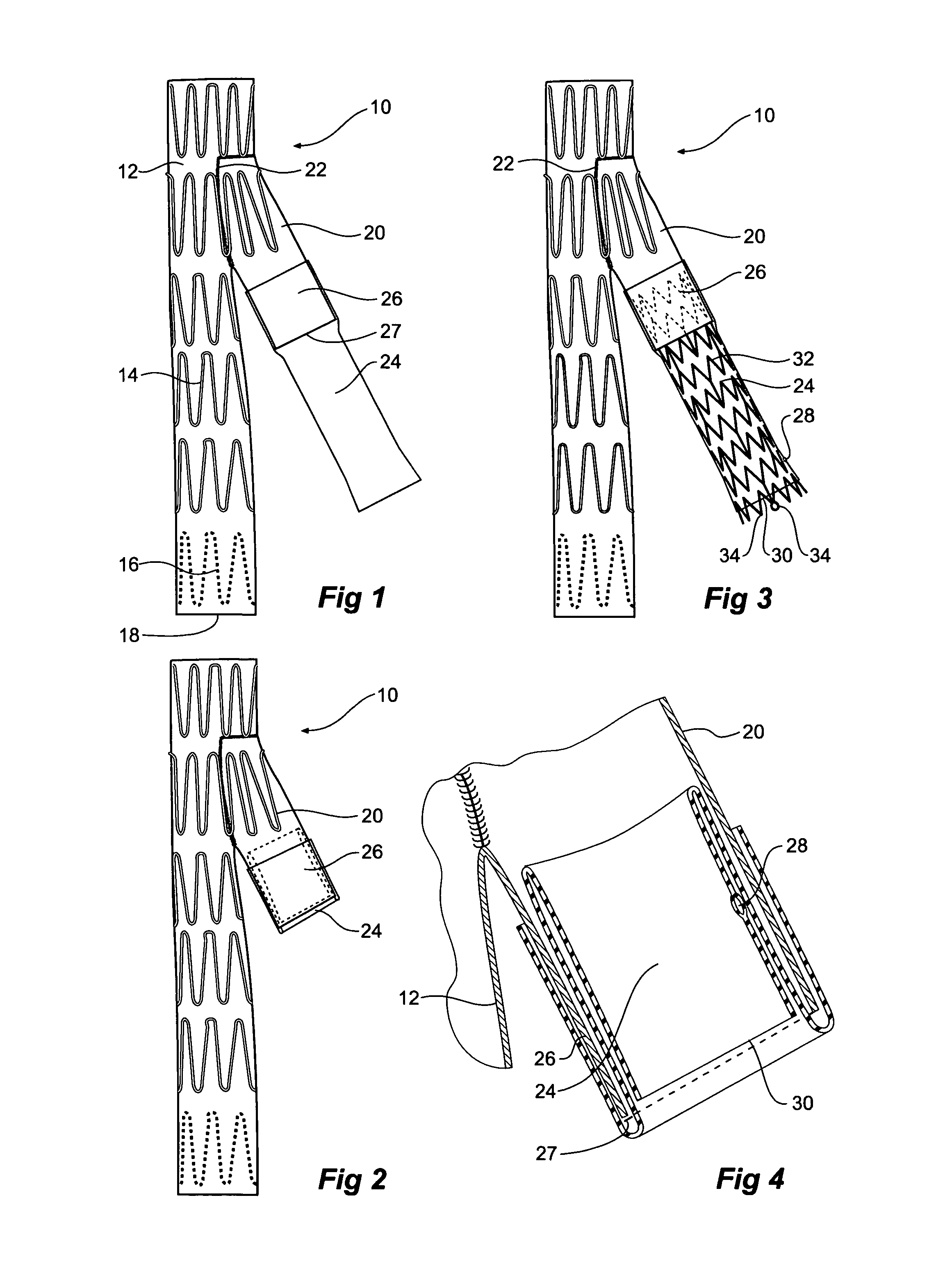
[0032]Now looking more closely at the first embodiment of the invention shown in FIGS. 1, 2, and 4 it will be seen that the stent graft 10 according to the present invention comprises a tubular body 12 of a biocompatible graft material such as Dacron supported by a plurality of self expanding zigzag Gianturco stents 14. At least the self expanding stent 16 at the distal end 18 of the stent graft 10 is internal and the other stents are preferably external. A side arm 20 is stitched into the main body by stitching 22 and extends away from the body at an angle towards the distal end of the stent graft. The side arm is formed from a biocompatible graft material such as Dacron. U.S. Provisional Patent Application Ser. No. 60 / 611,744, filed Sep. 21, 2004, U.S. patent application Ser. No. 11 / 231,621, filed Sep. 21, 2005, and Published on May 4, 2006, as U.S. Patent Application Publication No. US-2006 / 0095118-A1, and PCT Patent Publication No. WO 06 / 034276 entitled “Side Branch Stent Graft”...


PUM


Abstract

A stent graft (10) has a tubular body of a biocompatible material and a side arm (20) fastened to the tubular body. A tubular extension piece (24) is sealingly joined to the end of the side arm and extends from it. It can be joined with adhesive or stitching. The extension piece can be formed from an elastomeric biocompatible material such as Thoralon™. The extension piece can have a resilient reinforcement 44 embedded into it and extending longitudinally. The extension piece is tucked back into the side arm during deployment of the stent graft into a body lumen.

Description

CROSS-REFERENCE TO RELATED APPLICATIONS[0001]This application claims priority of provisional application Ser. No. 60 / 697,174, filed Jul. 7, 2005.TECHNICAL FIELD[0002]This invention relates to a medical device and more particularly to a medical device for endovascular deployment into a body lumen such as the vasculature of an animal or human.BACKGROUND OF THE INVENTION[0003]It is known to use branch vessel stent grafts deployed into vasculature of a human or animal to provide and alternate flow path where the vasculature has been damaged by accident or disease. The branch vessel stent graft allows an extension piece to be deployed from a main graft into a side vessel of the vasculature so that blood flow can enter the side vessel.[0004]The conventional procedure to treat branch vessels utilizes a balloon expandable covered stent which is deployed through the side arm of the stent graft to connect the side vessels to a bifurcated stent graft. The limitation of a delivery system for su...

Claims


Application Information

Patent Timeline
Patent Type & Authority Patents(United States)
IPC IPC(8): A61F2/07A61F2/06A61F2/89
CPCA61F2/07A61F2/89A61F2002/065A61F2002/067A61F2230/0067A61F2220/005A61F2220/0075A61F2230/005A61F2230/0054A61F2002/075
Inventor SUN, JICHAO
Owner COOK MEDICAL TECH LLC
Why Eureka
Try Eureka