Full bore cementable gun system

a cementable gun and full bore technology, applied in the field of completion techniques, can solve the problems of limited circulation of brine prior to well cleaning, and achieve the effect of enhancing perforation

Inactive Publication Date: 2010-03-30
BAKER HUGHES INC
View PDF24 Cites 69 Cited by
  • Summary
  • Abstract
  • Description
  • Claims
  • Application Information

AI Technical Summary

Problems solved by technology

Prior well cleaning such as with brine circulation is now limited to the region of the hanger and above.

Method used


Image

  • Full bore cementable gun system
  • Full bore cementable gun system
  • Full bore cementable gun system

Examples


Embodiment Construction

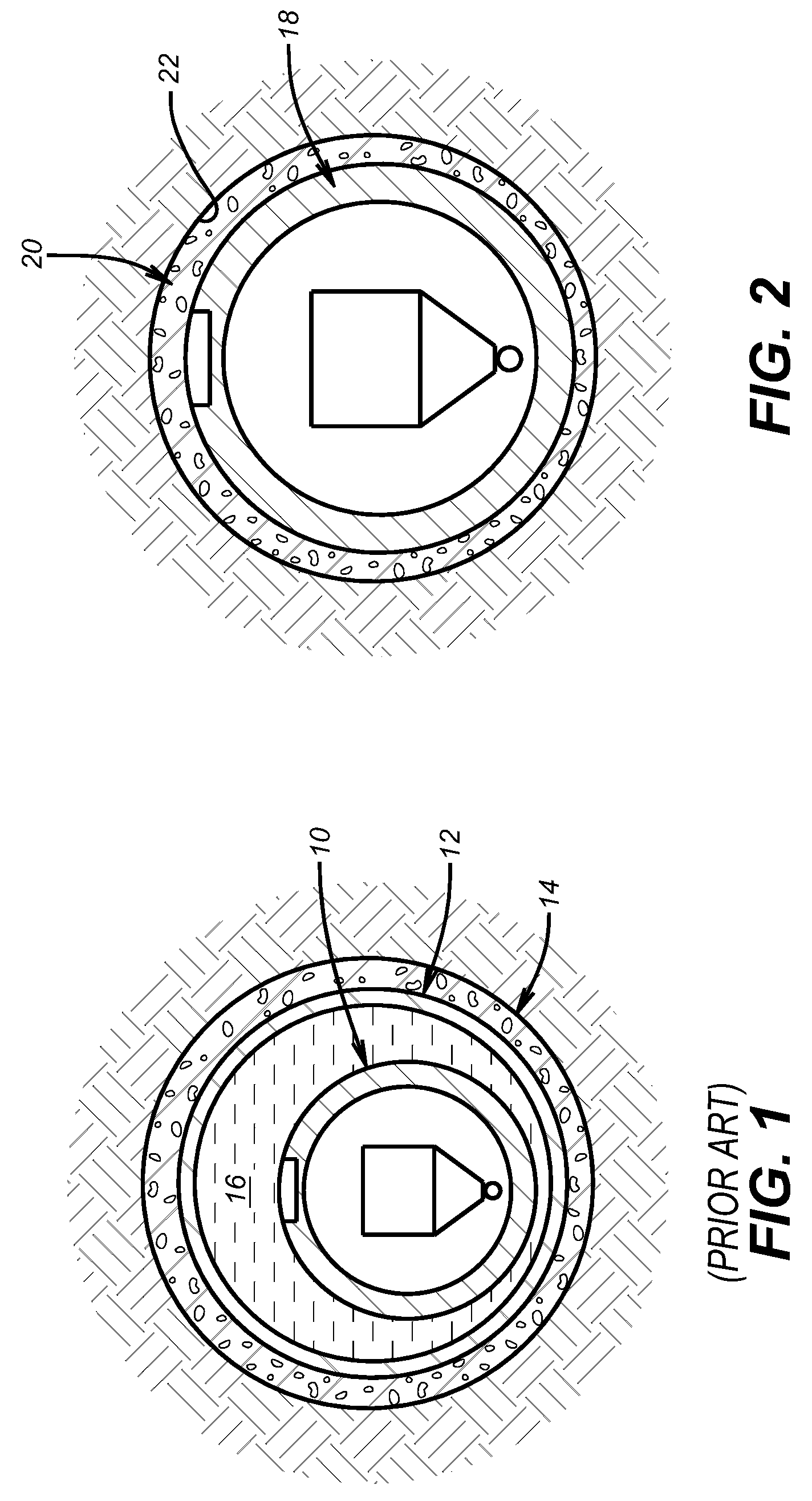
[0012]FIG. 1 illustrates the known way of completion where a perforating gun 10 is run through a casing or tubular 12 that has been cemented 14. To fit through the tubular 12 the gun or guns have to be dimensionally smaller. The guns 10 when fired have to penetrate the tubular 12. Long periods of brine circulation are needed to get the debris out of the tubular string 12 so that there is a brine solution 16 surrounding the gun 10 when it is introduced into the wellbore. The density of the shot used in the gun 10 is limited by its outer dimension limitation caused by the inside diameter of the tubular 12 though which the gun 10 is advanced before it is fired.

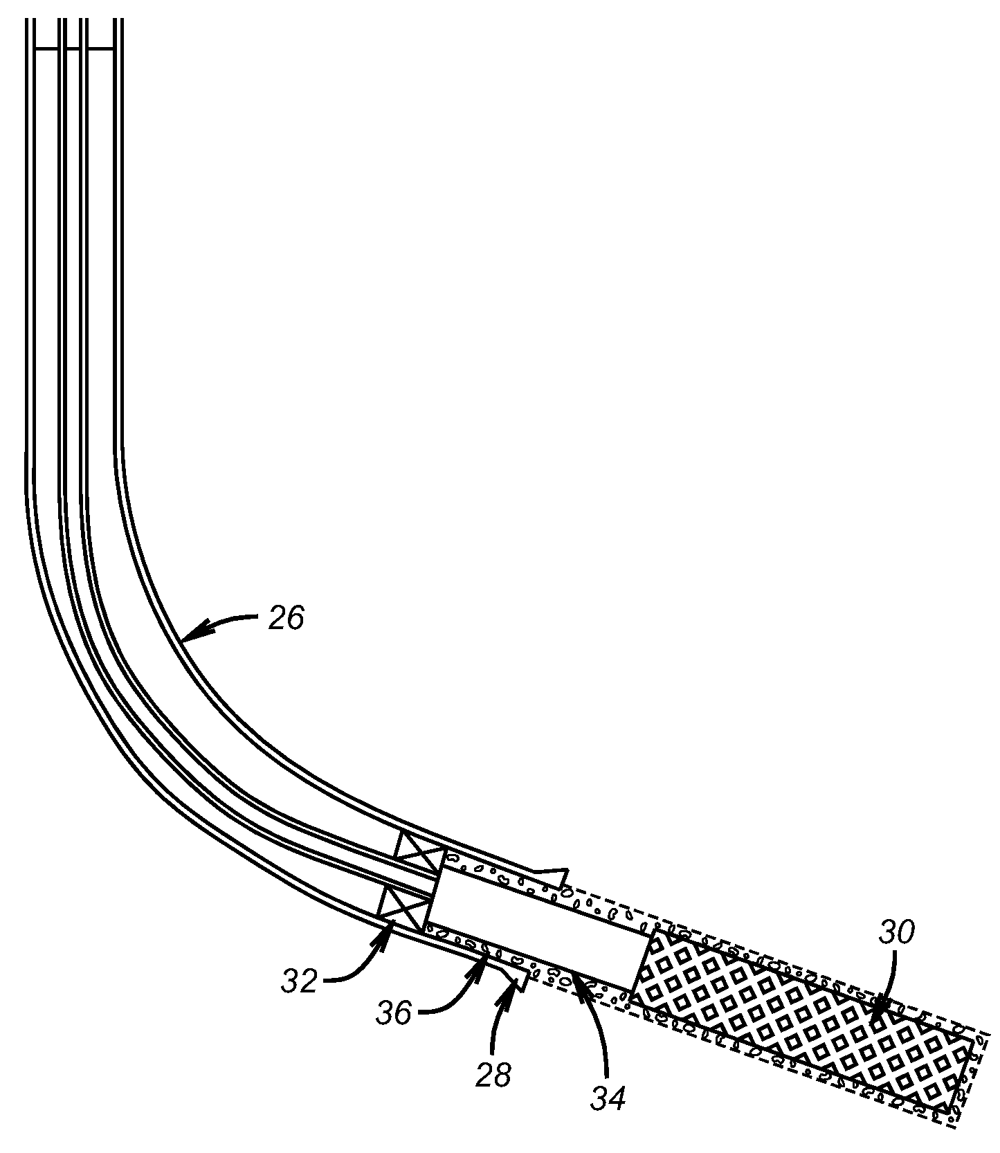
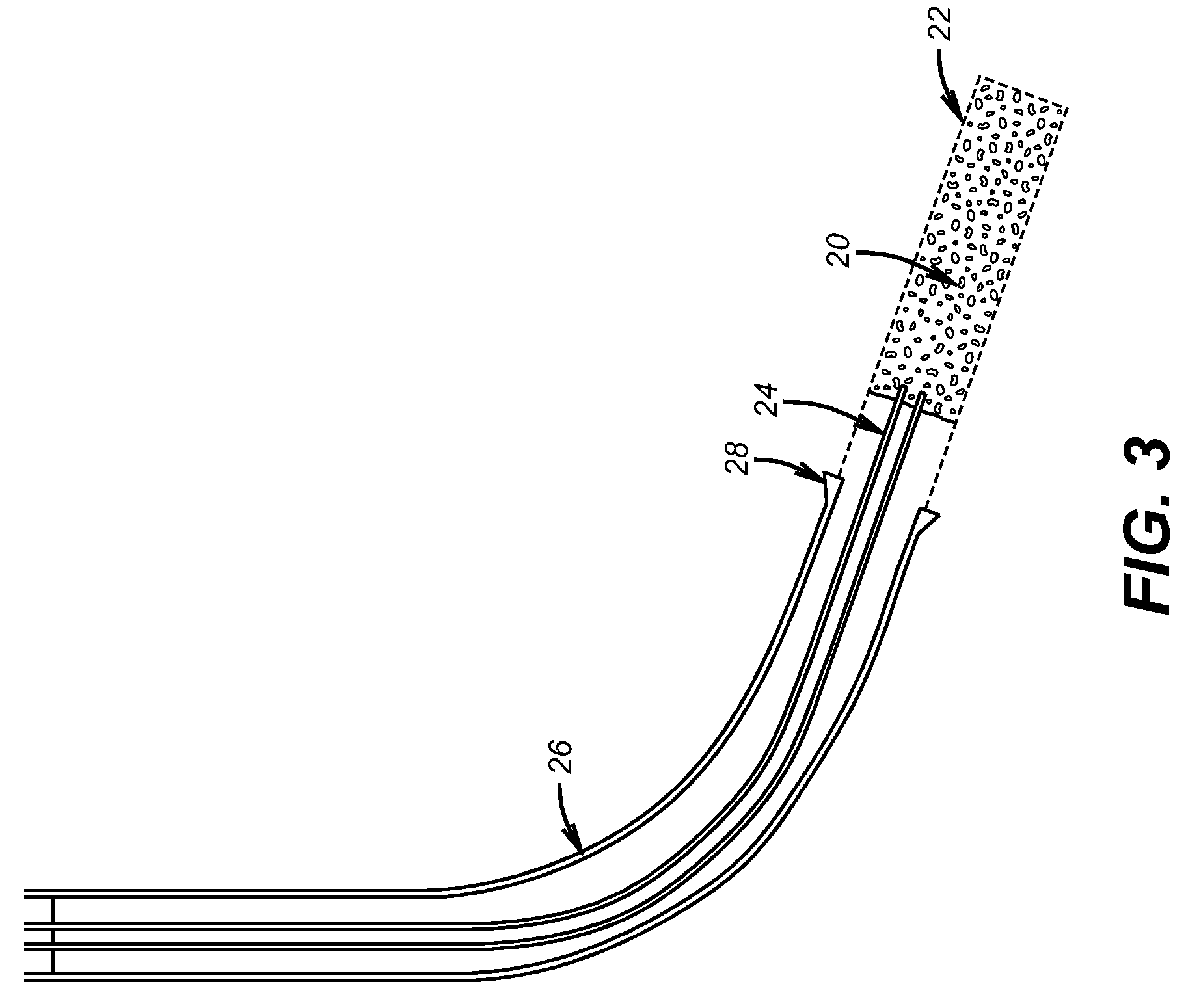
[0013]FIG. 2 illustrates the present invention and is better understood when looked at in conjunction with FIG. 3. The gun 18 is far larger than gun 10 of FIG. 1 because the tubular 12 no longer surrounds the gun 18. Instead the gun 18 is advanced into delivered cement 20 in open hole 22. As seen in FIG. 3 a string 24 delivers th...


PUM


Abstract

A completion method delivers cement to an open hole below a cemented casing. A gun or guns are run below a liner and a hanger and advanced into the cement before it sets up. With the gun and the liner surrounded in cement up to close to the hanger that supports the liner to the already cemented casing, the cement is allowed to set around the gun with no tubular surrounding the gun. The gun carries extra shot to enhance the perforation and can be fluid filled with clean fluid. Prior well cleaning such as with brine circulation is now limited to the region of the hanger and above. Production flow is through the perforations into the gun body allowing any residue of the explosive charge used to perforate to flow to surface.

Description

FIELD OF THE INVENTION[0001]The field of this invention is completion techniques and more particularly involving perforating through cement without a cemented casing, liner or other tubular in situ.BACKGROUND OF THE INVENTION[0002]Typically completions involve running in casing or hanging a liner and cementing it into position in the wellbore. Before running in a perforating gun the wellbore is generally circulated clean with brine so that the well is reasonably free of debris before the guns are set off. This circulation process can take days and is quite costly. Beyond that the casing or liner that is run in and cemented limits the gun size that can be run through it and that, in turn, limits the shot density in the gun.[0003]If a tube or passage, of sufficient cross sectional area to deliver cement to the borehole below the gun, were placed inside the gun, the space it occupied would restrict the volume available for perforating charges. This would compromise the quality of the p...

Claims


Application Information

Patent Timeline
Patent Type & Authority Patents(United States)
IPC IPC(8): E21B33/13E21B43/11
CPCE21B43/00E21B43/10E21B43/11
Inventor MARSH, ROGER J.
Owner BAKER HUGHES INC
Why Eureka
Try Eureka