Optical system and projection display device

a technology which is applied in the field of can solve the problems of increased manufacturing cost of conventional optical system and projection display device, complicated structure, etc., and achieve the effect of low manufacturing cos

Active Publication Date: 2010-03-30
JVC KENWOOD CORP +1
View PDF5 Cites 40 Cited by
  • Summary
  • Abstract
  • Description
  • Claims
  • Application Information

AI Technical Summary

Benefits of technology

[0018]Under the above-mentioned problems, an object of the present invention is to provide an optical system which can provide high-contrast images, multi-primary color images and 3-dimensional images by a structure for first dividing a light, which has been combined after modulating (1st. modulation) lights by the conventional 3-primary color devices, into halves and secondly modulating the so-divided lights by their exclusive signals (2nd. modulation). Another object of the present invention is provide an optical system and a projection display device both of which are low in manufacturing cost, needless of the adjustment in superimposing images and which can display even 3-dimensional images on a screen.

Problems solved by technology

In this way, the conventional optical system and projection display device are apt to be increased in manufacturing cost and complicated in structure due to the presence of two projectors 8A, 8B.

Method used


Image

  • Optical system and projection display device
  • Optical system and projection display device
  • Optical system and projection display device

Examples


fourth embodiment

[0062]the present invention will be described with reference to FIG. 8.

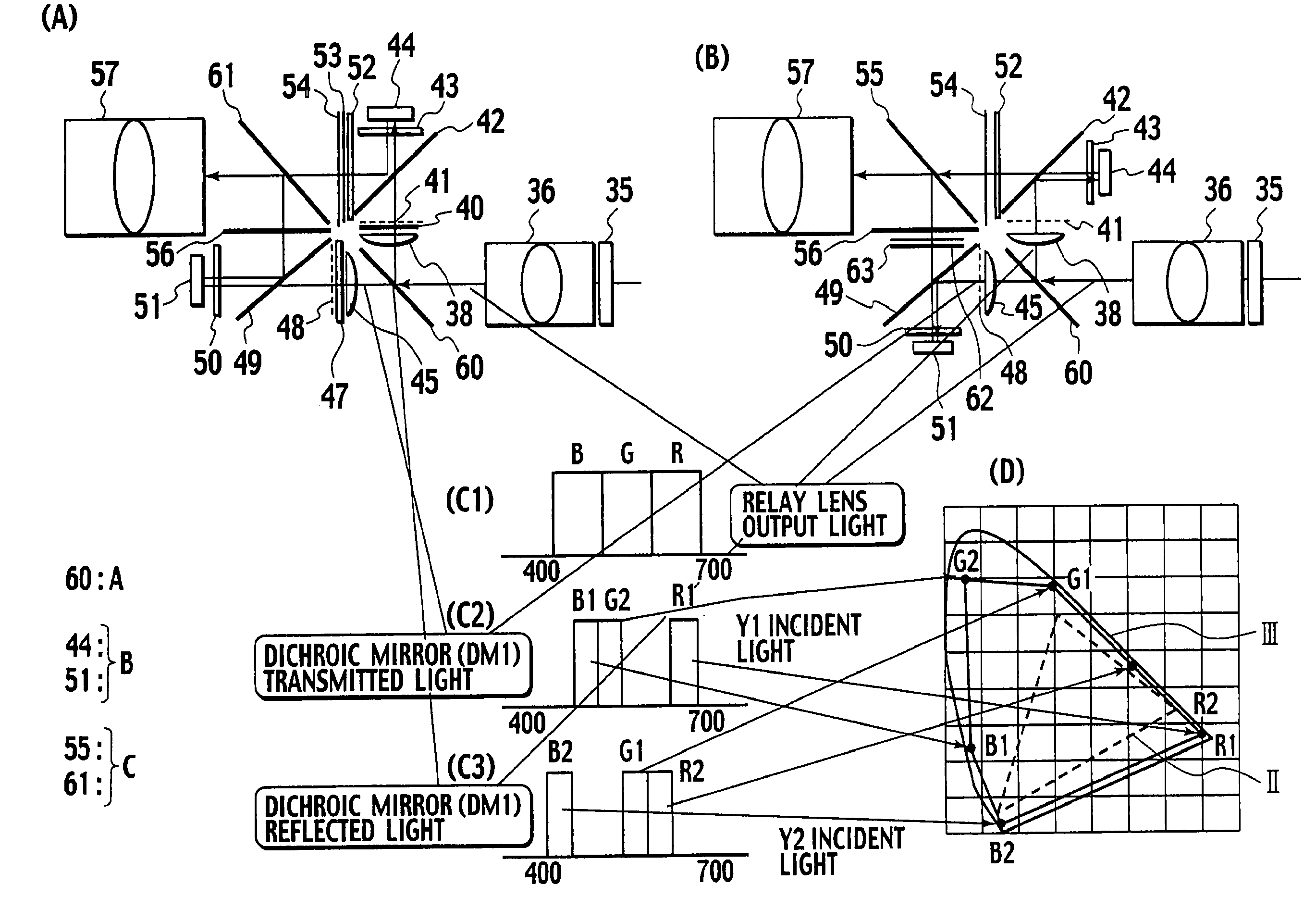
[0063]In FIG. 8, a part (A) shows a constitution of the substantial part of the optical system in accordance with the fourth embodiment of the present invention. In the fourth embodiment, elements identical to those of the third embodiment in (B) of FIG. 7 are indicated with the same reference numerals and their overlapping descriptions are eliminated. The feature of the fourth embodiment resides in the provision of a dichroic mirror 65 having the band-separation characteristic in (B2), (B3) of FIG. 8 or (C2), (C3) of FIG. 8 in place of the dichroic mirror 60 of the third embodiment. Note that in FIG. 8 a color spectroscope A includes the dichroic mirror 65.

[0064]In (A) of FIG. 8, the composite light from the first modulation optical system 101 (FIG. 4) has a spectrum shown in (B1) of FIG. 8. This composite light is transmitted through the 1:1 relay lens 36 thereby to enter the dichroic mirror 65 through which th...

third embodiment

[0066]The lights modulated by the Y1 device 44 and the Y2 device 51 are transmitted through the similar optical system to the third embodiment and subsequently subjected to PS composition. Thereafter, the resulting composite light is projected on a screen (not shown) through the Y1Y2 projector lens 57.

[0067]In the fourth embodiment of (A) of FIG. 8, as shown with a spectrum in (B1) of FIG. 8, if the incident light from the first modulation optical system has the red light band (R) and the blue light band (B) established broader than the green light band (G), the dichroic mirror 65 has a band-separation characteristic to divide the red light band and the blue light band into halves respectively. Consequently, the X-Y chromaticity diagram of light of the fourth embodiment represents a reproducible color gamut of five primary colors shown with solid line IV in (D) of FIG. 8. Obviously, this reproducible color gamut of five primary colors is broader than the reproducible color gamut II ...

fifth embodiment

[0072]the present invention will be described with reference to FIG. 9.

[0073]In FIG. 9, a part (B) shows a constitution of the substantial part of the optical system in accordance with the fifth embodiment of the present invention. In the fifth embodiment, elements identical to those of the fourth embodiment in (B) of FIG. 8 are indicated with the same reference numerals and their overlapping descriptions are eliminated. The feature of the fifth embodiment resides in the provision of a dichroic mirror 66 having the band-separation characteristic in (B2), (B3) of FIG. 9 in place of the dichroic mirror 60 of the third embodiment. Note that in FIG. 9 a color spectroscope A includes the dichroic mirror 66.

[0074]In (A) of FIG. 9, the composite light from the first modulation optical system 101 (FIG. 4) has a spectra shown in (B1) of FIG. 9. This composite light is transmitted through the 1:1 relay lens 36 thereby to enter the dichroic mirror 66 through-which the green light component G1 ...


PUM


Abstract

Light in primary colors RGB modulated in a first modulation optical system is transmitted through a relay lens (36) and further divided into a P-polarized light and an S-polarized light by a PS separation wire grid (37). The S-polarized light is transmitted through a wavelength spectral filter (39) to select red / green / blue light components R1, G1, B1 of 615, 515, 450 nm in wavelength, which are then modulated by a Y1 device (44). The P-polarized light is transmitted through a wavelength spectral filter (46) to select red / green / blue light components R2, G2, B2 of 650, 550, 475 nm in wavelength, which are then modulated by a Y2 device (51). The 3 -primary color lights modulated by the Y1 / Y2 devices (44), (51) are combined with each other at a PS composite wire grid (55) to project a synthetic light on a screen.

Description

BACKGROUND OF THE INVENTION[0001]1. Field of the Invention[0002]The present invention relates to an optical system and a projection display device. Particularly, the present invention relates to an optical system and a projection display device both of which can provide high-contrast images and multi-primary color / 3-dimensional images for a projection type projector.[0003]2. Description of Related Art[0004]Conventionally, a 3-panel type projector using three pieces (red, green, blue) of modulation devices is general in the projection display device (projector). Depending on the kind of devices, the 3-panel type projectors comprise LCD (Liquid Crystal Display) projector, DLP (Digital Light Processing) projector, LCOS (Liquid Crystal on Silicon) projector and so on. However, there is a possibility that precise color reproduction couldn't be attained by only a single 3-panel type projector since its reproducible area is limited to an area represented as the sum of 3-dimensional color v...

Claims


Application Information

Patent Timeline
Patent Type & Authority Patents(United States)
IPC IPC(8): G03B21/28G06T15/00G09G1/28G09G5/02G03B21/00G03B35/26H04N5/74H04N9/31H04N13/04
CPCH04N9/3105H04N9/3126H04N9/3197H04N13/0422H04N13/0431H04N13/0434H04N13/0459G03B21/005G03B21/26H04N13/324H04N13/334H04N13/337H04N13/363
Inventor YOSHIMURA, MAKOTOFURUYA, MASATOKANAZAWA, MASARUKUSAKABE, YUICHI
Owner JVC KENWOOD CORP
Why Eureka
Try Eureka