Annuloplasty device having shape-adjusting tension filaments

a tension filament and annuloplasty technology, applied in the field of mitral valve regurgitation treatment, can solve the problems of distorting the shape of the mitral valve, reducing the ejection volume of the left ventricle, and allowing the left ventricle to compensate with a larger stroke volume, so as to reduce the regurgitation through the mitral valve

Active Publication Date: 2010-04-13
MEDTRONIC VASCULAR INC
View PDF4 Cites 96 Cited by
  • Summary
  • Abstract
  • Description
  • Claims
  • Application Information

AI Technical Summary

Benefits of technology

[0009]Another aspect of the invention provides a method for treating mitral valve regurgitation and includes preloading a tensioning device into an internal lumen of a delivery catheter. The tensioning device comprises a flexible ring, a plurality of anchoring members attached to the flexible ring, and a tensioning filament attached to the flexible ring. The method further comprises deploying the tensioning device from the catheter adjacent to the mitral valve, positioning the flexible ring against the annulus of the mitral valve, and embedding the anchoring members into the annulus. Next, the lengths of segments of the tensioning filament are adjusted, causing the shape of the flexible ring to change. Altering the shape of the flexible ring causes the shape of the annulus to change, thus reducing regurgitation through the mitral valve.

Problems solved by technology

This results in reduced ejection volume from the left ventricle, causing the left ventricle to compensate with a larger stroke volume.
However, the increased workload eventually results in dilation and hypertrophy of the left ventricle, further enlarging and distorting the shape of the mitral valve.
If left untreated, the condition may result in cardiac insufficiency, ventricular failure, and ultimately death.
This is a complex, invasive surgical procedure with the potential for many complications and a long recovery period.
Rigid annuloplasty rings have the disadvantage of causing the mitral valve annulus to be rigid and unable to flex in response to the contractions of the ventricle, thus inhibiting the normal, three dimensional movement of the mitral valve that is required for it to function optimally.
This eventually leads to scar tissue formation and loss of flexibility and function of the mitral valve.
Similarly, combination rings must generally be sutured in place and also cause scar tissue formation and loss of mitral valve flexibility and function.
While likely to be effective for modest changes in the size or shape of the mitral annulus, this device may cause significant tissue compression in patients requiring a larger change in the configuration of the mitral annulus.
Alternatively, the coronary sinus in a particular individual may not wrap around the heart far enough to allow effective encircling of the mitral valve, making this treatment ineffective.
Furthermore, leaving a device in the coronary sinus may result in formation and breaking off of thrombus that may pass into the right atrium, right ventricle, and ultimately the lungs causing a pulmonary embolism.
Another disadvantage is that the coronary sinus is typically used for placement of a pacing lead, which may be precluded with the placement of the prosthesis in the coronary sinus.

Method used


Image

  • Annuloplasty device having shape-adjusting tension filaments
  • Annuloplasty device having shape-adjusting tension filaments
  • Annuloplasty device having shape-adjusting tension filaments

Examples


Embodiment Construction

[0021]Throughout this specification, like numbers refer to like structures.

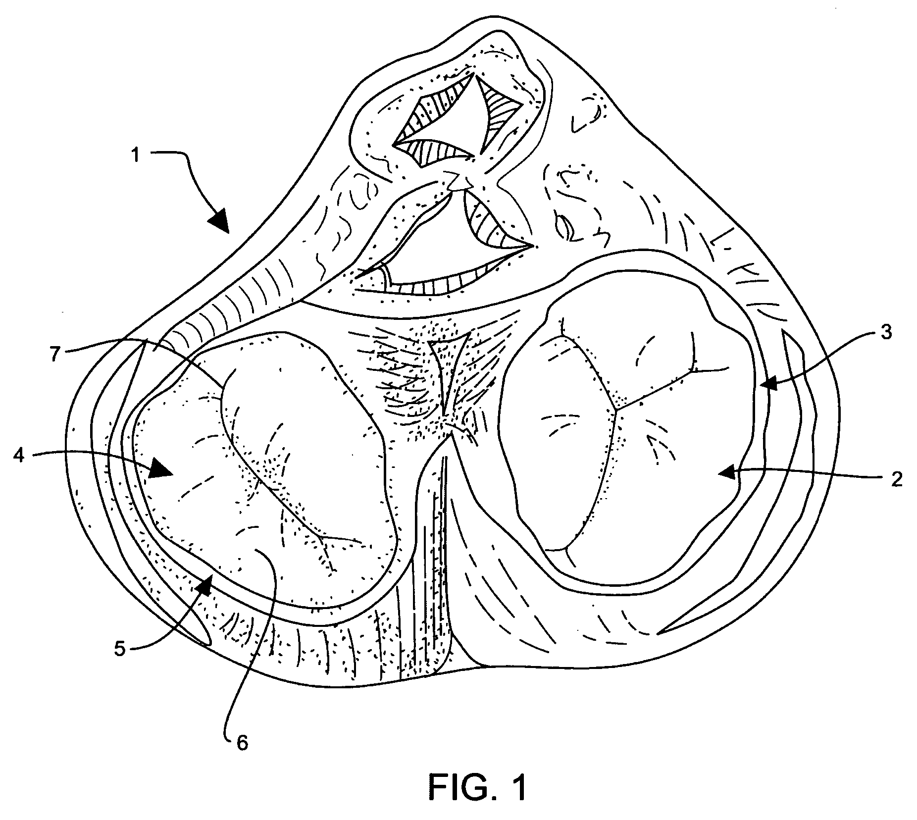
[0022]Referring to the drawings, FIG. 1 shows a cross-sectional view of heart 1 having tricuspid valve 2 and tricuspid valve annulus 3. Mitral valve 4 is adjacent mitral valve annulus 5. Mitral valve 4 is a bicuspid valve having anterior cusp 7 and posterior cusp 6. Anterior cusp 7 and posterior cusp 6 are often referred to, respectively, as the anterior and posterior leaflets.

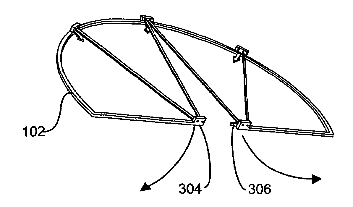
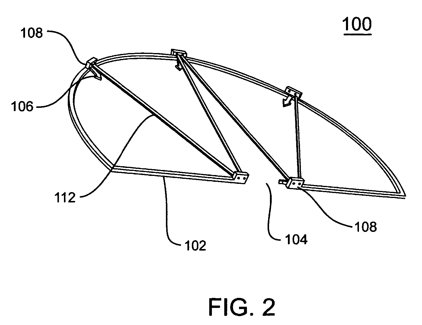
[0023]Referring to the drawings, FIG. 2 portrays a tensioning device 100 for treating mitral valve regurgitation. Tensioning device 100 includes annuloplasty ring 102. Annuloplasty ring 102 is made of a flexible, biocompatible material that has “shape memory” so that ring 102 can be extended into an elongated configuration and inserted into a delivery catheter, but will re-assume its original shape and dimensions when deployed adjacent to the mitral valve annulus 5. In one embodiment of the invention, flexible ring 102 comprises nitinol...


PUM


Abstract

A system for treating mitral valve regurgitation includes a tensioning device having a flexible annuloplasty ring, a plurality of anchoring members and a tensioning filament attached to the flexible ring. One embodiment of the invention includes a method for attaching a flexible annuloplasty ring to the annulus of a mitral valve, and adjusting the lengths of segments of the tension filament attached to the flexible ring in order to exert force vectors on the annulus, thereby reshaping the mitral valve annulus so that the anterior and posterior leaflets of the mitral valve close completely during ventricular contraction.

Description

FIELD OF THE INVENTION[0001]This invention relates generally to the treatment of mitral valve regurgitation and particularly to a method and device to improve mitral valve coaptation in a diseased heart.BACKGROUND[0002]The heart is a four-chambered pump that moves blood efficiently through the vascular system. Blood enters the heart through the vena cava and flows into the right atrium. From the right atrium, blood flows through the tricuspid valve and into the right ventricle, which then contracts and forces blood through the pulmonic valve and into the lungs. Oxygenated blood returns from the lungs and enters the heart through the left atrium and passes through the mitral valve into the left ventricle. The left ventricle contracts and pumps blood through the aortic valve into the aorta and to the vascular system.[0003]The mitral valve consists of two leaflets (anterior and posterior) attached to a fibrous ring or annulus. In a healthy heart, the mitral valve leaflets close during ...

Claims


Application Information

Patent Timeline
Patent Type & Authority Patents(United States)
IPC IPC(8): A61F2/24
CPCA61F2/2454A61F2/2445
Inventor BLOOM, ELIOTRAFIEE, NASSER
Owner MEDTRONIC VASCULAR INC
Why Eureka
Try Eureka