Golf driver impact analyzer

a golf driver and impact analyzer technology, applied in golf, golf accessories, sport equipment, etc., can solve the problems of other limitations of the related art, and achieve the effect of reducing the number of players

Inactive Publication Date: 2010-06-01
FITZGERALD LISA M
View PDF43 Cites 14 Cited by
  • Summary
  • Abstract
  • Description
  • Claims
  • Application Information

AI Technical Summary

Benefits of technology

[0030]This invention is directed to the golf swing analyzer that provides a learning tool for golfers to help develop golf backswing consistency and club face angle. A golf ball will travel in the desired straight path if two conditions are met: the swing path must be in line with the desired ball trajectory, and the club face must be aligned at a right angle (90 degrees) to the ball trajectory. To gage the club angle relative to swing path, a fence is placed perpendicular to the club face. During a golf swing, an air flow along this fence is created by the swinging motion of the club. For a perfect square shot, the pressures are equal on both sides of the fence; otherwise, as the fence angle changes relative to air flow, one side compacts the air, creating a high-pressure area while at the same time the opposite side dams the air flow and creates a low-pressure area. A differential pressure transducer detects this pressure difference on each side of the fence. When the ball is struck, a microphone in the device detects the ball impact and a microprocessor interprets the fence position relative to air flow based on the pressure transducer output. A microprocessor-driven speaker outputs a unique audio tone at the moment of ball impact. With this audible tone it can be determined if the club face angle was open, closed or square, relative to the swing path.

Problems solved by technology

However, the game of golf is premised upon a golf swing which is at best unnatural.
Other limitations of the related art will become apparent to those skilled in the art upon a reading of the specification and a study of the drawings.

Method used


Image

  • Golf driver impact analyzer
  • Golf driver impact analyzer
  • Golf driver impact analyzer

Examples


Embodiment Construction

Definitions

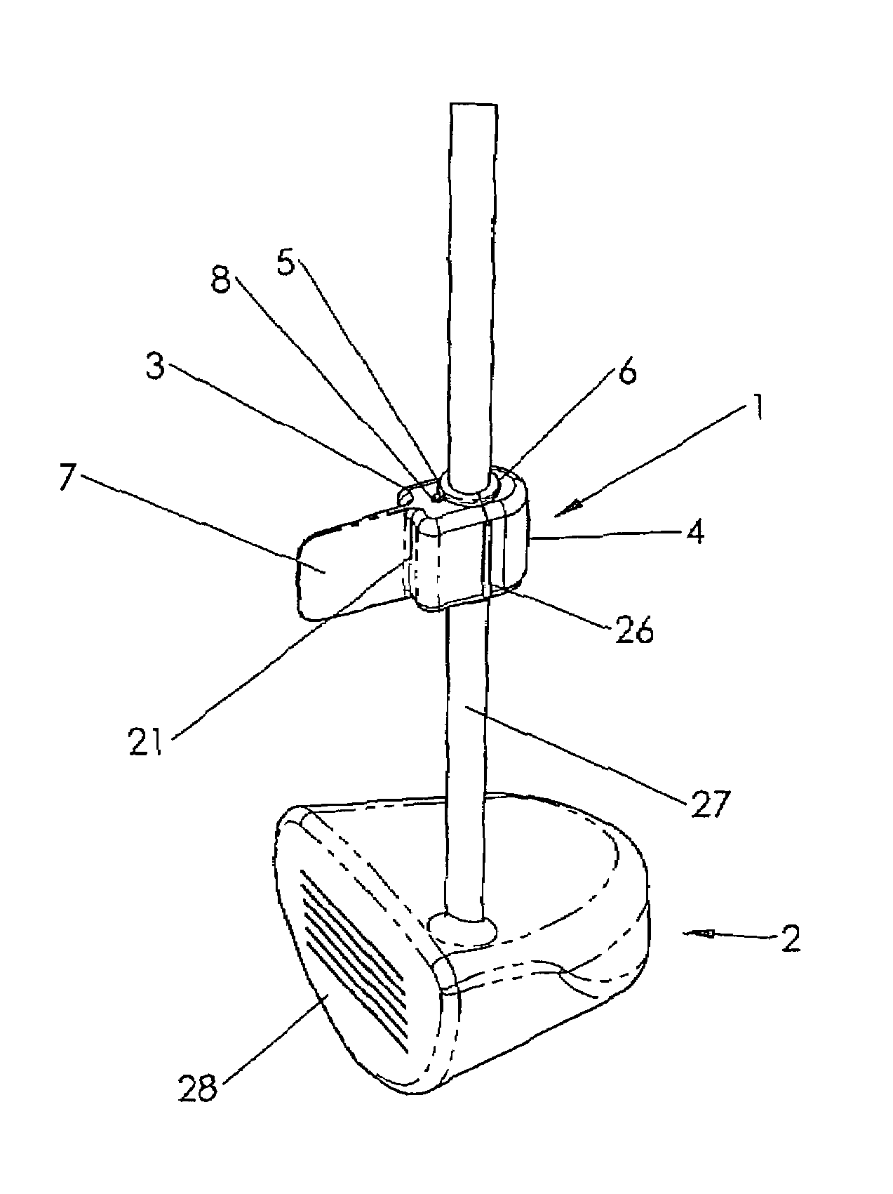
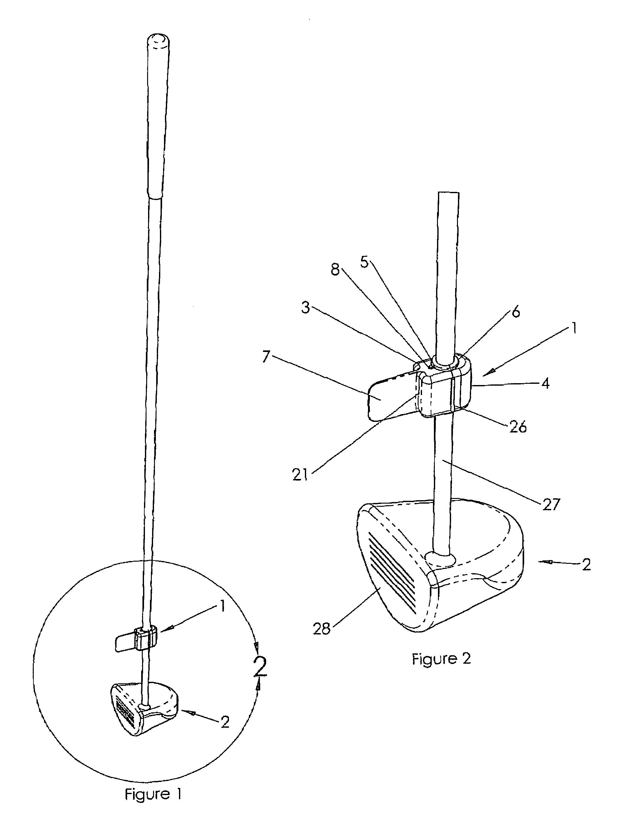
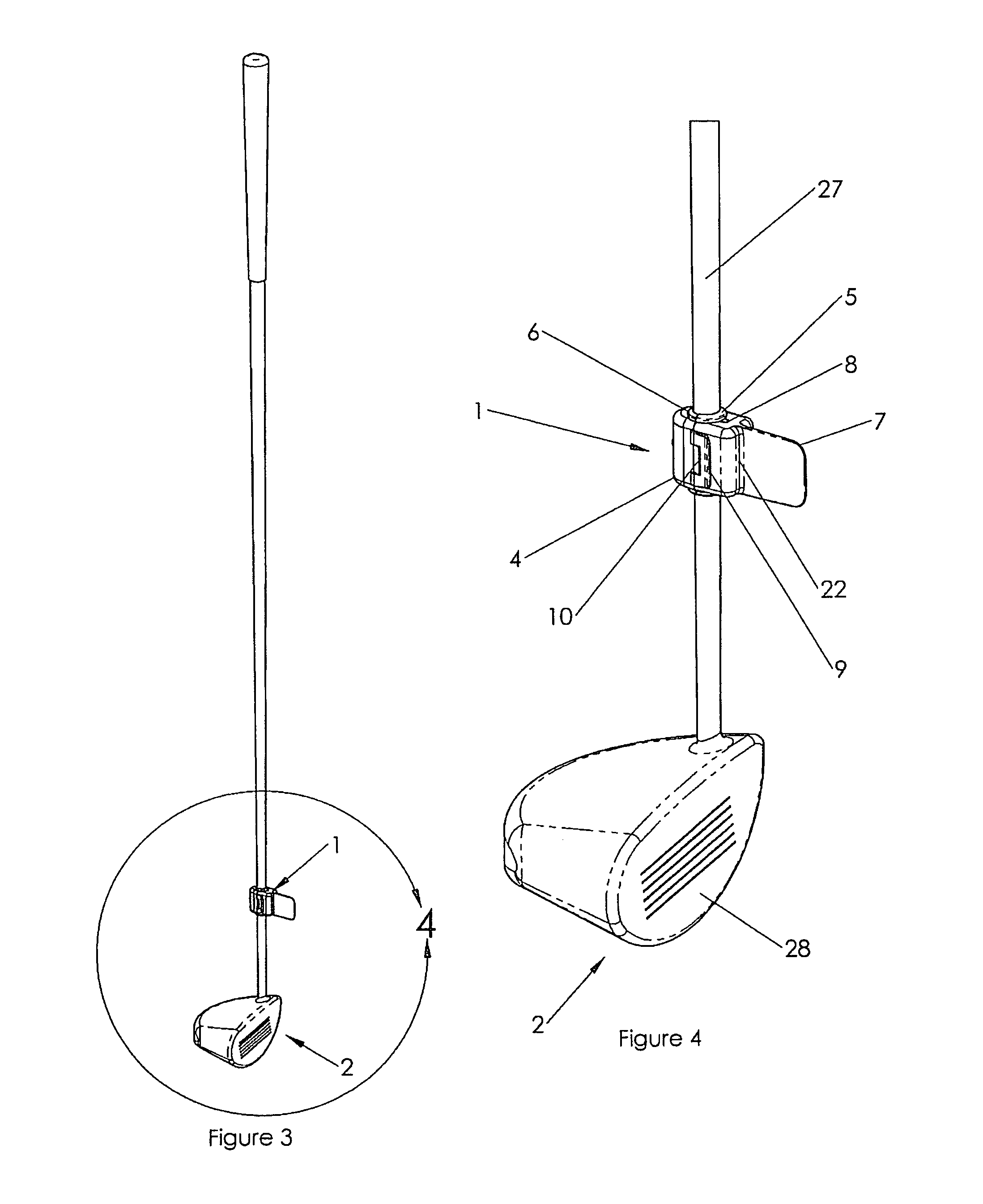
[0053]1 impact analyzer[0054]2 golf club[0055]3 analyzer housing[0056]4 housing retainer[0057]5 front grip[0058]6 rear grip[0059]7 fence[0060]8 speaker aperture[0061]9 latch[0062]10 latch retainer[0063]11 flexible circuit board[0064]12 tilt switch[0065]13 battery[0066]14 positive contact[0067]15 negative contact[0068]16 contact retaining screw[0069]17 pressure transducer[0070]18 microprocessor[0071]19 speaker[0072]20 anti-slip boss[0073]21 left pressure aperture[0074]22 right pressure aperture left pressure transducer[0075]23 inlet right pressure transducer[0076]24 inlet[0077]25 microphone[0078]26 living hinge[0079]27 club shaft[0080]28 club face[0081]29 battery retainer boss[0082]30 golf ball[0083]31 hole[0084]32 air flow direction[0085]33 swing path direction[0086]34 ball path direction[0087]35 high pressure area[0088]36 low pressure area[0089]37 position arrow[0090]38 circuit board assembly[0091]39 rear friction pad[0092]40 circuit retainer boss

[0093]Ref. FIGS. 1, 2, 3...


PUM


Abstract

A golf swing analyzer providing a learning tool for golfers to help improve golf backswing and club face angle consistency. To gage the club angle relative to swing path, a fence is placed and held on the shaft perpendicular to the club face. During a golf swing, an air flow along this fence is created by the swinging motion of the club. For a perfect square shot, the pressures are equal on both sides of the fence; otherwise, as the fence angle changes relative to air flow, one side compacts the air, creating a high-pressure area while at the same time the opposite side dams the air flow and creates a low-pressure area. A differential pressure transducer detects this pressure difference on each side of the fence. When the ball is struck, a microphone in the device detects the ball impact and a microprocessor interprets the fence position relative to air flow based on the pressure transducer output. A microprocessor-driven speaker outputs a unique audio tone at the moment of ball impact which indicates whether the club face angle was open, closed or square, relative to the swing path.

Description

CROSS-REFERENCE TO RELATED APPLICATIONS[0001]Not applicableSTATEMENT REGARDING FEDERALLY SPONSORED RESEARCH OR DEVELOPMENT[0002]Not applicableINCORPORATION-BY-REFERENCE OF MATERIAL SUBMITTED ON A COMPACT DISC[0003]Not applicableBACKGROUND OF THE INVENTION[0004]1. Field of the Invention[0005]This invention relates generally to practice and corrective devices associated with the golf swing and the game of golf and more particularly to a golf club swinging guide which provides immediate audible indicia reflective of any misalignment between the golf swing itself and the direction the striking face of the golf club head faces at the moment of golf ball impact.[0006]2. Description of Related Art[0007]The world of golf has attracted a vast mountain of players, competitors and golf club equipment, not to mention the vast investment in golf courses themselves. However, the game of golf is premised upon a golf swing which is at best unnatural. Developing a correct swing for consistent power ...

Claims


Application Information

Patent Timeline
Patent Type & Authority Patents(United States)
IPC IPC(8): A63B69/36
CPCA63B69/3632A63B2220/803A63B2220/80A63B2220/30
Inventor FITZGERALD, LISA M.
Owner FITZGERALD LISA M
Why Eureka
Try Eureka