Image processing apparatus

a technology of image processing and motion data, applied in the field of image processing apparatus, can solve the problems of how a load on the computer is to be reduced during the calculation of motion data with high accuracy, and achieve the effects of reducing image blur, high quality, and high accuracy

Active Publication Date: 2010-08-10
MORPHO INC
View PDF11 Cites 11 Cited by
  • Summary
  • Abstract
  • Description
  • Claims
  • Application Information

AI Technical Summary

Benefits of technology

[0017]The present invention was made in view of the problem, and it is an object of the present invention to provide an image processing apparatus which can calculate motion data with high precision by simpler processing with a smaller amount of data and lighter load on a computer and allows the correction of image blur due to a hand movement in photo-shooting, generation of high quality photographs by using the technology and capture of a subject properly in moving-picture shooting.

Problems solved by technology

By the way, when the function for generating motion data such as a motion vector, an affine parameter or the like is implemented by not special hardware but a computer having a calculation function, how a load on the computer is to be reduced during calculating motion data with high accuracy is a problem.

Method used


Image

  • Image processing apparatus
  • Image processing apparatus
  • Image processing apparatus

Examples


first embodiment

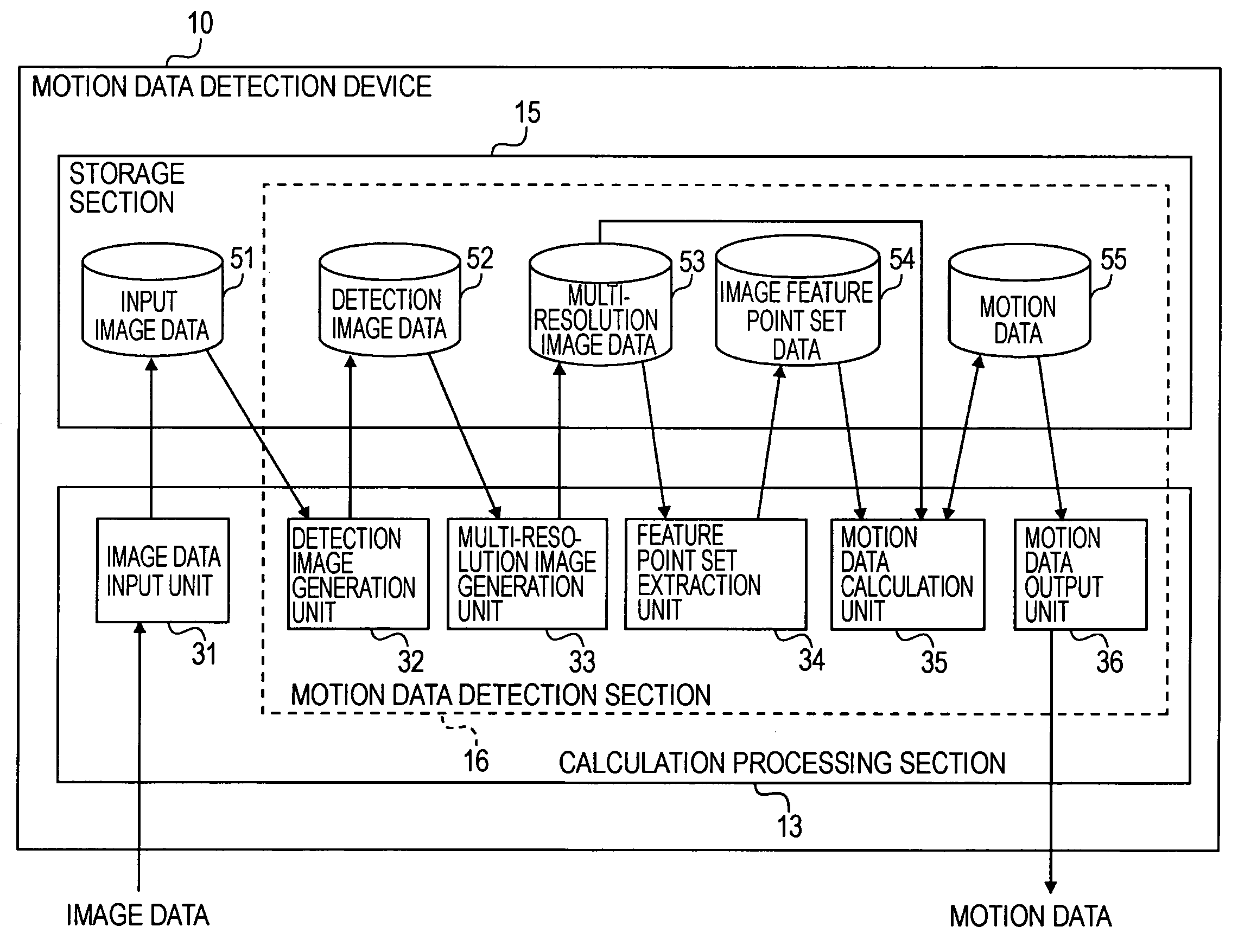
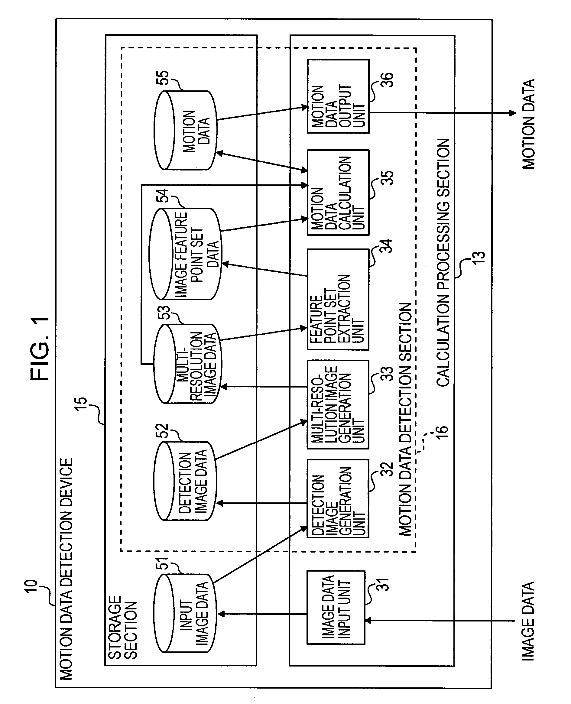
[0054]FIG. 1 is a block diagram of a motion data detection apparatus 10 according to this embodiment. The apparatus 10 receives the input of multiple images and calculates motion data among images.

[0055]Here, the motion data detection apparatus 10 includes a calculation processing section 13 for calculating motion data such as a motion vector and an affine parameter based on input image data, and a storage section 15 for storing input image data and / or motion data.

[0056]The calculation processing section 13 includes an image data input unit (function) 31 for receiving the input of image data from an external device such as a camera, a communication network and a recording medium and storing them in the storage section 15, a detection image generation unit (function) 32 for generating an image (detection image) from which motion data is detected based on input image data, a multi-resolution image generation unit (function) 33 for generating image data of multiple resolution levels by...

second embodiment

[0089]FIG. 7 is a block diagram of an image processing apparatus 1 according to this embodiment. Here, the image processing apparatus 1 includes a motion data detection device 10, an image synthesis unit 37 for synthesizing an image by using motion data generated by the device 10 and multiple pieces of input image data, and a synthesized image output unit 38 for outputting the generated synthesized image data. The units 37 and 38 are implemented as functions of a CPU.

[0090]Next, operations of the image processing apparatus 1 according to this embodiment will be described. Since the operations of the motion data detection device 10 are the same as those of the first embodiment, the description will be omitted here.

[Image Synthesis Process]

[0091]In order to perform processing for deforming one image or processing for deforming and superposing multiple images, processing is required for obtaining colors of pixels from the position of an image before deformation to the position of the d...

third embodiment

[0111]A case that the present invention is applied to a moving picture will be described as the next third embodiment.

[Outline of Hand-Movement Correction in Moving Pictures of High-Degree of Freedom]

[0112]In a conventional and general electronic moving picture hand-movement correction (i.e. anti-shake technology), hand-movement correction is achieved by detecting how much a shot frame displaces from a reference frame and outputting a corrected frame by moving the shot frame in parallel based on a detected travel. For example, as shown in FIG. 13A, a corrected frame (output frame) is assumed to set as indicated by the dashed line in order to shoot moving pictures of a person. Next, when the shot frame is displaced by a hand-movement as shown in FIG. 13B, the corrected frame (output frame) is moved in parallel as indicated by the dashed line and output in response thereto. The amount of displacement is detected by a gyrosensor and / or image processing.

[0113]However, in the hand-moveme...


PUM


Abstract

Multi-resolution images of a reference image and a target image are generated. Then, whole-range matching is performed on an image of a lower resolution to detect a two-dimensional displacement between the images. Block matching is performed on an image of a higher resolution to detect a displacement at each feature point. The accuracy of motion data is increased by correcting the motion data with an image of a higher resolution by using the previously calculated motion data of the lowest resolution through higher resolutions as an initial value.

Description

BACKGROUND OF THE INVENTION[0001]1. Field of the Invention[0002]The present invention relates to a technology that allows shooting a high quality still and / or moving picture. In particular, it is an object of the present invention to provide a computer image processing apparatus for images shot with a camera, which allows generating a clear image free from blur by hand movement in shooting the image and allows shooting a moving picture tracking a target subject by preventing the jitter of an image due to a hand movement by capturing the subject properly.[0003]2. Description of the Related Art[0004]Conventionally, a large amount of moving picture data is reduced by calculating motion vectors between moving picture frames and generating moving picture data with the motion vectors and a reference image.[0005]On the other hand, a technology has been disclosed for correcting a blur in an image due to a hand movement in shooting it by calculating motion vectors between multiple still imag...

Claims


Application Information

Patent Timeline
Patent Type & Authority Patents(United States)
IPC IPC(8): G06K9/36
CPCG06T7/2073G06T5/003G06T2207/10016G06T7/207
Inventor HIRAGA, MASAKIHABUKA, KENSUKE
Owner MORPHO INC
Why Eureka
Try Eureka