Temperature sensor for a resistance thermometer, in particular for use in the exhaust gas system of combustion engines

Active Publication Date: 2010-08-24
SENSATA TECHNOLOGIES INC
View PDF13 Cites 12 Cited by
  • Summary
  • Abstract
  • Description
  • Claims
  • Application Information

AI Technical Summary

Benefits of technology

[0041]It is a particular advantage of the invention that the temperature sensor can be prefabricated in standard dimensions and can then be connected to a holder adapted to the conditions of the particular application, to form a temperature sensor ready for being mounted, for example for being screwed in.
[0042]Certain embodiments of the invention are illustrated in the attached draw

Problems solved by technology

The demands placed on temperature sensors that are to be used in the exhaust gas system of combustion engines, which in part oppose each other, make it difficult to find a temperature sensor for use in the exhaust gas system of comb

Method used


Image

  • Temperature sensor for a resistance thermometer, in particular for use in the exhaust gas system of combustion engines
  • Temperature sensor for a resistance thermometer, in particular for use in the exhaust gas system of combustion engines
  • Temperature sensor for a resistance thermometer, in particular for use in the exhaust gas system of combustion engines

Examples


Embodiment Construction

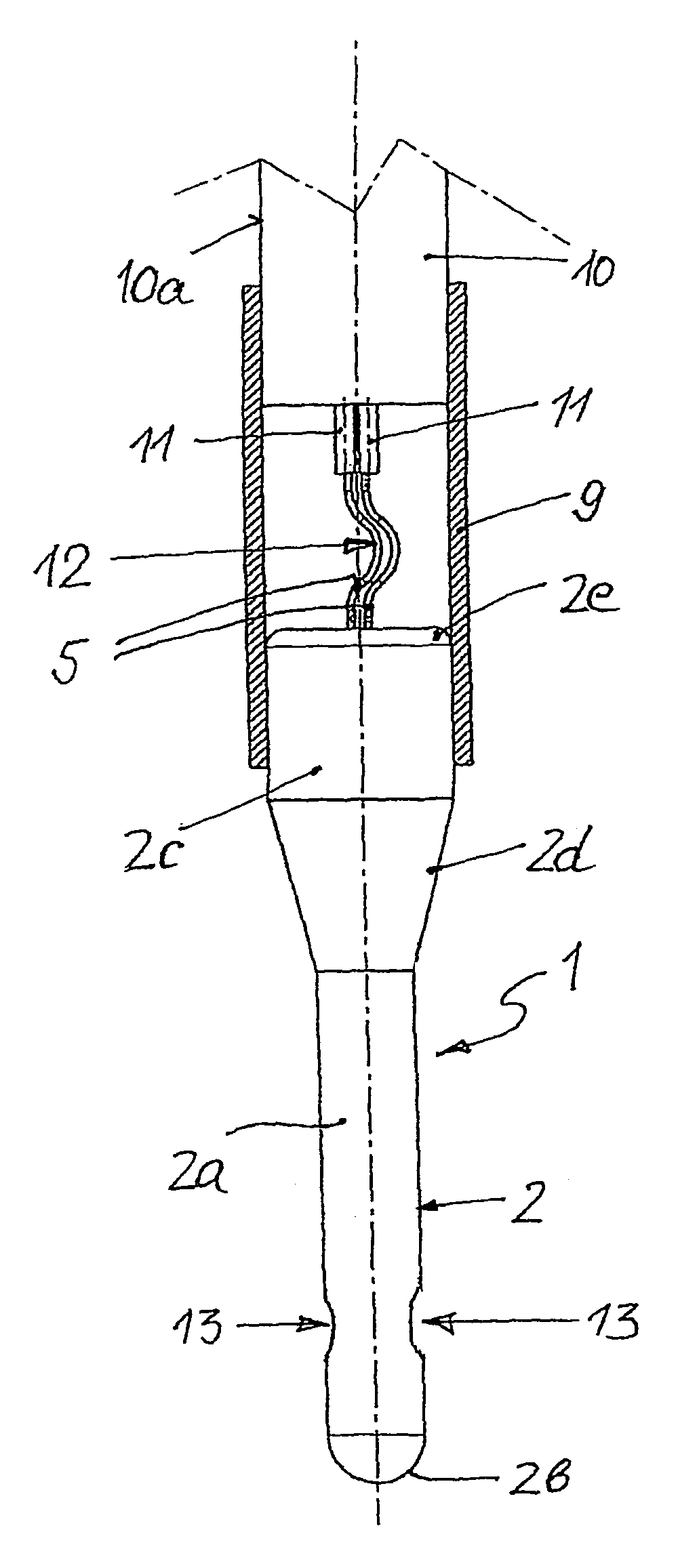
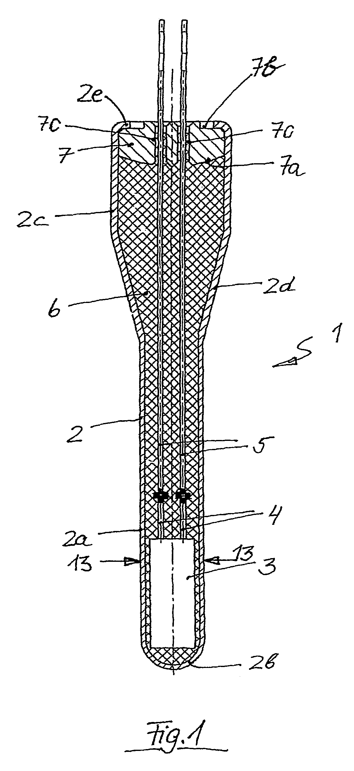
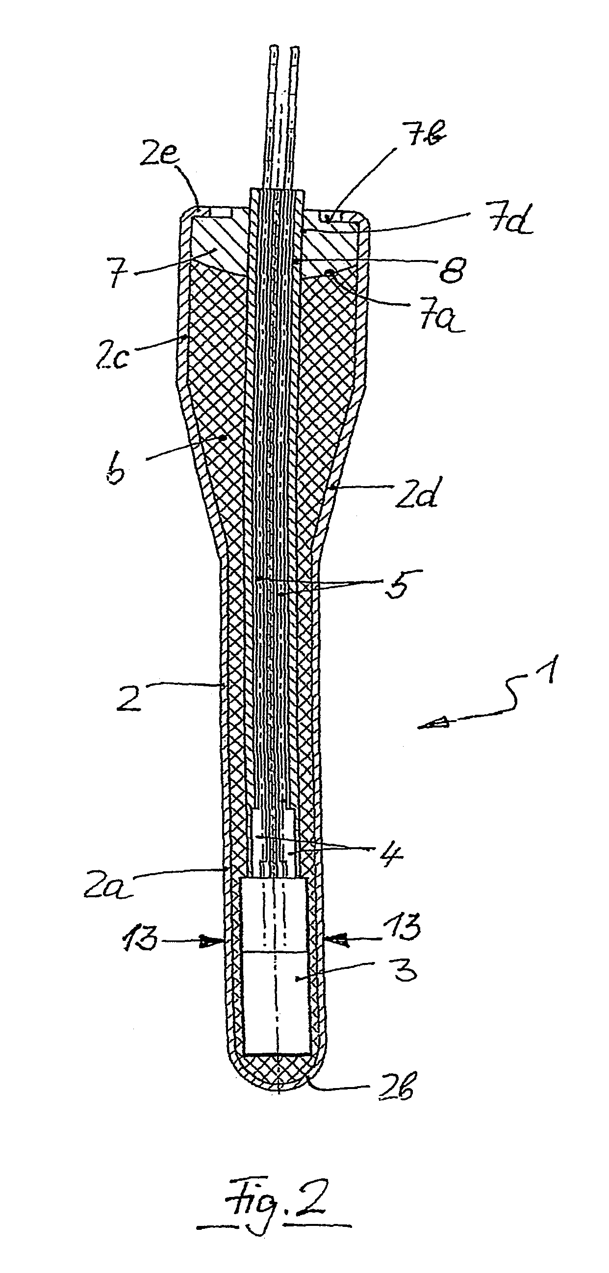
[0046]The temperature sensor 1 illustrated in FIG. 1 comprises a measuring resistor 3 with supply lines 4, extended in length by supply wires 5, in a protective tube 2. The measuring resistor 3, the supply lines 4 and the supply wires 5 are embedded in a ceramic or mineral filler 6.

[0047]Preferably, the measuring resistor 3 is a thin ceramic plate on which a platinum resistor is printed.

[0048]The protective tube 2 has a slim cylindrical forward section 2a with a closed rounded tip 2b, a cylindrical rear section 2c of a diameter larger than the diameter of the forward section 2a, and a conical transition portion 2d. Alternatively, the tip 2b may be flat and / or the transition portion 2d may be stepped.

[0049]The measuring resistor 3 and the diameter of the forward portion 2a of the protective tube are adapted one to the other so that an unnecessarily big spacing is avoided between the measuring resistor 3 and the protective tube 2.

[0050]The protective tube 2 is made from a highly heat-...


PUM


Abstract

The invention describes a temperature sensor for a resistance thermometer comprising
    • an electric measuring resistor (3) the resistance material of which consists either of a ceramic material or of a metallic resistance material in combination with a ceramic or a mineral carrier,
    • a protective tube (2) comprising a closed tip (2b) and a rear end that provides an access to the inner space of the protective tube (2) and that contains the measuring resistor (3) closely adjacent the closed tip (2b) of the protective tube (2),
    • at least one supply line (5) that is brought out through the rear end of the protective tube (2),
and an electrically insulating filler (6) based on a ceramic or a mineral material that fills the space between the protective tube (2) on the one side and the measuring resistor (3) and its at least one supply line (4, 5) on the other side. It is provided according to the invention that the packing density of the filler (6) has a gradient in lengthwise direction of the protective tube (2).

Description

BACKGROUND OF THE INVENTION[0001]1. Field of the Invention[0002]The present invention relates to a temperature sensor for a resistance thermometer comprising an electric measuring resistor the resistance material of which consists either of a ceramic material or of a metallic resistance material in combination with a ceramic or a mineral carrier, a protective tube comprising a closed tip and a rear end that provides an access to the inner space of the protective tube and that contains the measuring resistor closely adjacent the closed tip of the protective tube, at least one supply line that is brought out through the rear end of the protective tube, and an electrically insulating filler based on a ceramic or a mineral material that fills the space between the protective tube on the one side and the measuring resistor and its at least one supply line on the other side. A temperature sensor of that kind has been known from DE 44 24 384 C2. It comprises a measuring resistor made from ...

Claims


Application Information

Patent Timeline
IPC IPC(8): G01K7/00G01K1/00H01C1/03
CPCG01K1/08G01K7/16G01K2205/04F01N11/002F01N2560/06G01K7/18
Inventor HOUBEN, HANSZAISER, RUDIGERMAYR, FRIEDRICHBUCK, HELMUTMOHL, MARKUSHARTMANN, ROBERTLEHMANN, HEINERSCHNEIDER, WERNERMARTO, ARNOKASIMIRSKI, HANS-PETER
Owner SENSATA TECHNOLOGIES INC
Why Eureka
Try Eureka