Jump rope system

a rope system and rope handle technology, applied in skipping ropes, gymnastic exercise, sport apparatus, etc., can solve the problems of limited speed at which the attached rope or cable element can be rotated by conventional jump rope, the resistance of the rope or cable element to conventional rotation, and the substantial problems of conventional jump rope still remain unresolved

Active Publication Date: 2010-09-07
JUMP ROPE SYST LLC
View PDF9 Cites 12 Cited by
  • Summary
  • Abstract
  • Description
  • Claims
  • Application Information

AI Technical Summary

Problems solved by technology

While conventional jump ropes have improved over time, substantial problems with conventional jump ropes still remain unresolved.
A first substantial problem with convention jump ropes may be that the constructional form of the jump rope handles limits the rate at which the attached rope or cable element of the jump rope can be spun or turned.
One aspect of this problem may be the level of resistance to rotation of the rope or cable element by conventional jump rope handles.
A second aspect of this problem may be that the rope or cable element attaches too closely or too far from the jump rope handle.
Attachment of the rope or cable element too close to the handle may result in contact between the cable element and the handle during turns of the rope or cable element.
As the lever arm increases in length, the difficulty in controlling the motion correspondingly generated in the handles can increase to an extent that the rate at which the rope or cable element turns can not be increased.
A third aspect of this problem can be that attachment of the cable to the handle does not allow the cable to swivel on the cable axis or allow the cable to pivot relative to the handle.
Alteration in the configuration of the rope or cable element can limit the rate at which the rope or cable element can be turned or make controlling the turn or spin more difficult.

Method used


Image

  • Jump rope system
  • Jump rope system
  • Jump rope system

Examples


Embodiment Construction

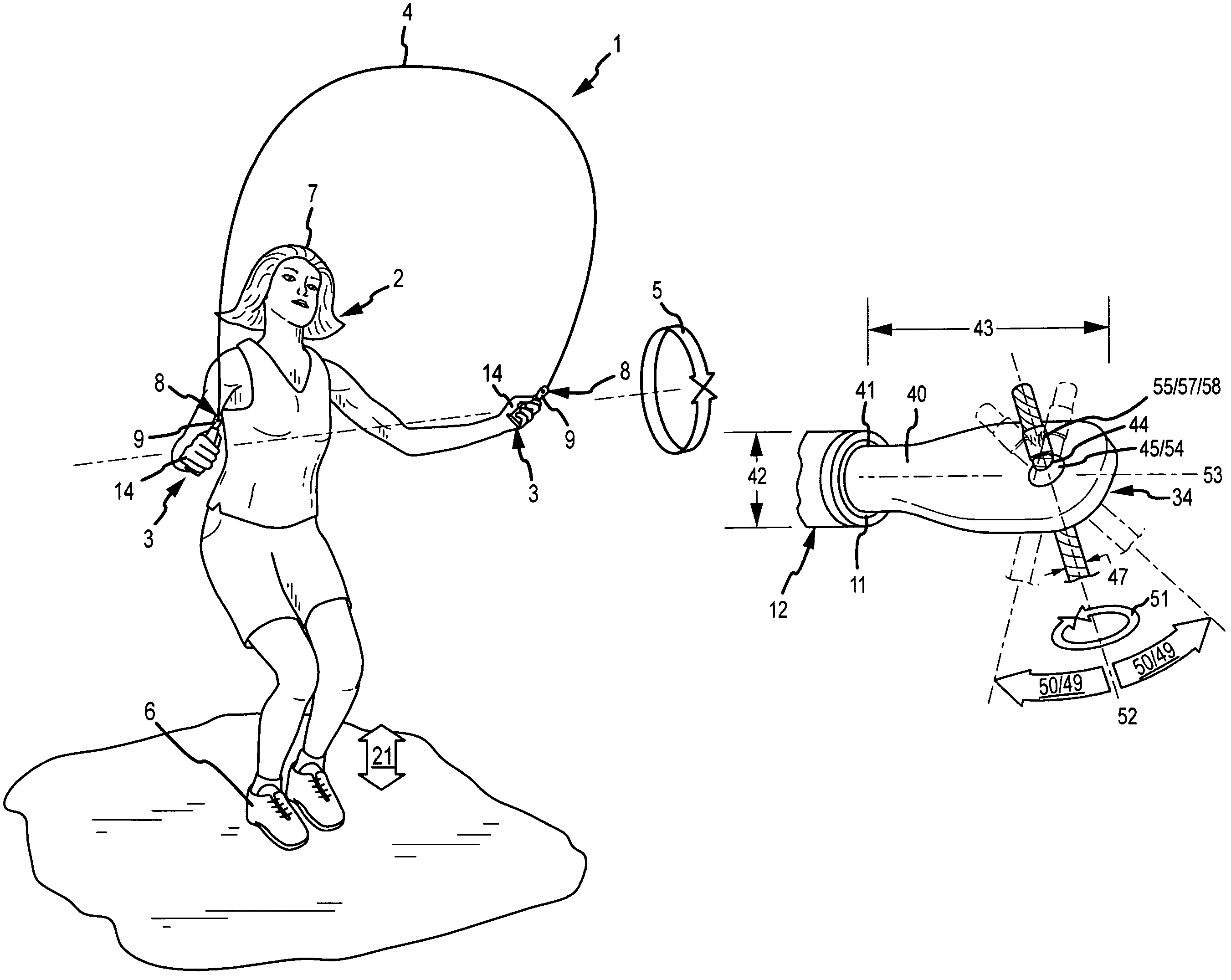
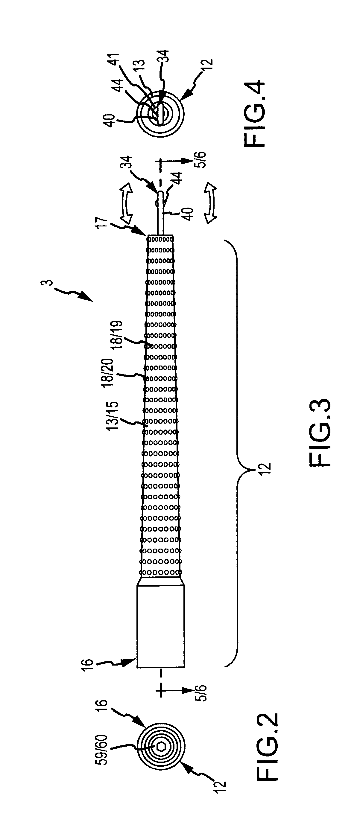
[0020]A jump rope which provides a pair of handles each handle providing a shaft coaxially rotatably engaged to a first bearing element and a second bearing element which attaches to a corresponding one of the opposed ends of a cable element.

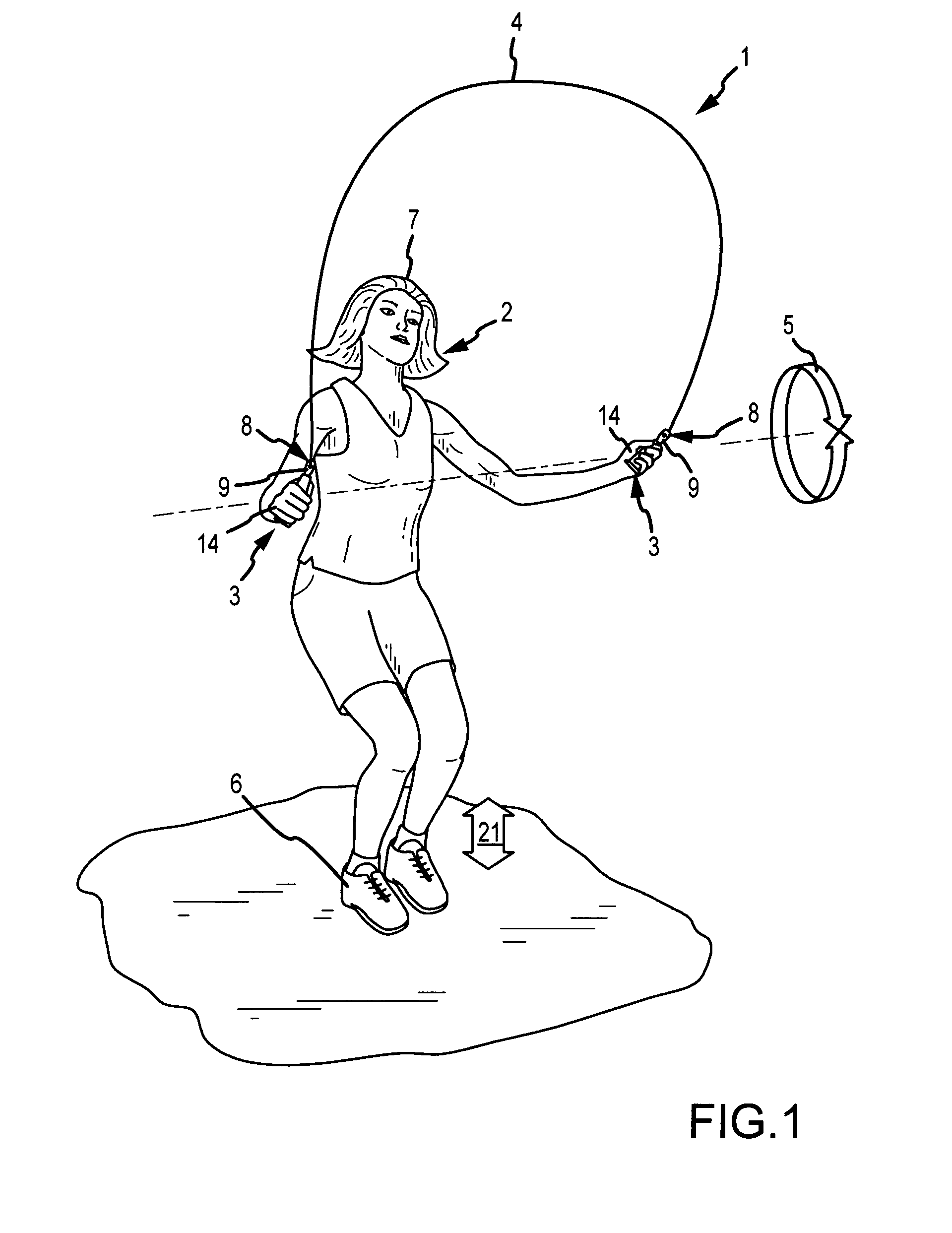
[0021]Now referring primarily to FIG. 1, which depicts a particular non-limiting method of using the inventive jump rope (1), a jumper (2) by gripping each of a pair of handles (3) can cause a cable element (4) attached to each of the pair of handles (3) to turn (5). Jumping over the turned cable element (4) so that the cable element (4) passes under the feet (6) and over the head (7) allows the jumper (2) to perform a basic jump (21). By attaching each one of a pair of opposed cable ends (8) of the cable element (4) to a shaft (9) (see also FIGS. 5-7) coaxially rotatably engaged to a first bearing element (10) and a second bearing element (11) retained in each one of the pair of handles (3), the cable element (4) can turn (5) in lesser amount t...


PUM


Abstract

A jump rope which provides a pair of handles each handle providing a shaft coaxially rotatably engaged to a first bearing element and a second bearing element which attaches to a corresponding one of the opposed ends of a cable means.

Description

I. BACKGROUND[0001]A jump rope which provides a pair of handles each handle providing a shaft coaxially rotatably engaged to a first bearing element and a second bearing element which attaches to a corresponding one of the opposed ends of a cable element.[0002]Rope jumping also referred to as rope skipping, skip roping, and jump rope is a skilled activity. There are literally thousands of jump rope skills which rope jumpers strive to achieve at increasingly greater jump rope spin or turn rates. While conventional jump ropes have improved over time, substantial problems with conventional jump ropes still remain unresolved.[0003]A first substantial problem with convention jump ropes may be that the constructional form of the jump rope handles limits the rate at which the attached rope or cable element of the jump rope can be spun or turned. One aspect of this problem may be the level of resistance to rotation of the rope or cable element by conventional jump rope handles. The greater ...

Claims


Application Information

Patent Timeline
Patent Type & Authority Patents(United States)
IPC IPC(8): A63B5/20
CPCA63B5/20A63B2209/02
Inventor BORTH, PAUL E.METZ, MARY L.
Owner JUMP ROPE SYST LLC
Why Eureka
Try Eureka