
Jump rope with resistance hand grips

a technology of resistance and rope, applied in the direction of skipping rope, gymnastic exercise, sport apparatus, etc., can solve the problems of reducing the exercise time, so as to reduce the relative distance and enable the flexing motion of the device

Inactive Publication Date: 2010-09-14
RIVERA III NICHOLAS
View PDF10 Cites 12 Cited by
  • Summary
  • Abstract
  • Description
  • Claims
  • Application Information

AI Technical Summary

Benefits of technology

[0015]A further object of the jumping rope with resistance hand grips provides for flexing the grip assemblies to a closed position while jumping rope or alternately flexed without utilizing the jump rope, thereby providing an exercising means.
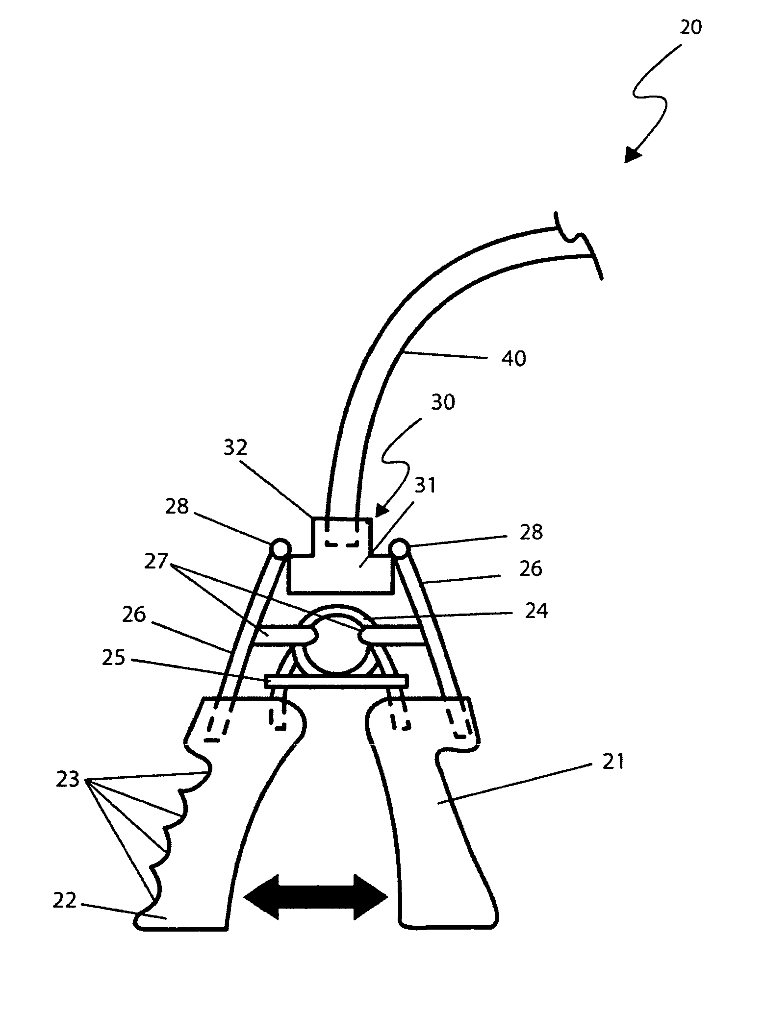
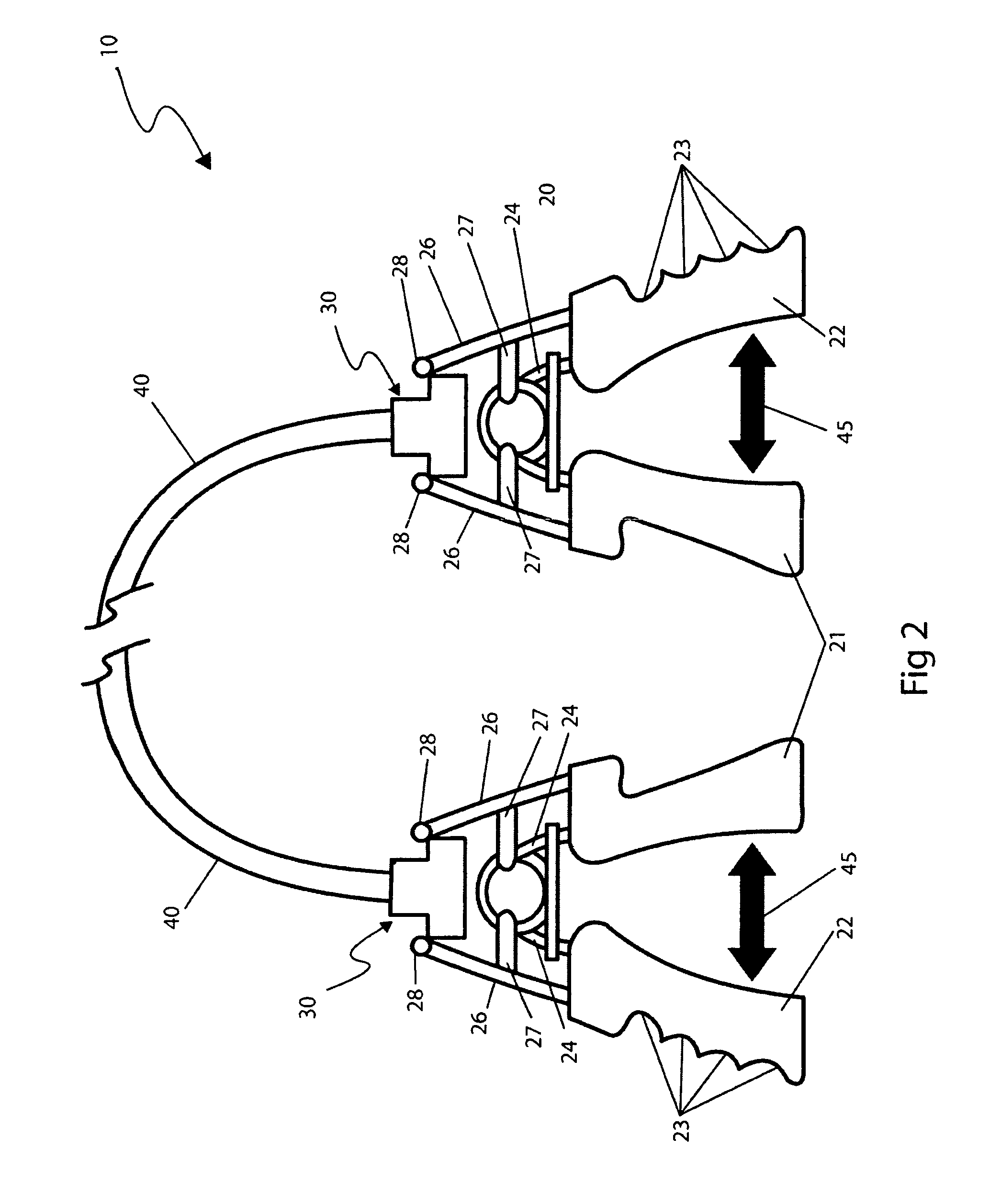
[0017]Still a further object of the jump rope with resistance hand grips provides for a grip assembly with a finger grip portion comprising four (4) finger relief areas along an outer edge positioned to correspond to a user's fingers for additional comfort.
[0018]Yet another object of the jump rope with resistance hand grips may provide an enhanced gripping surface utilizing methods such as, but not limited to: a molded-in knurled pattern thereupon external surfaces, a sprayed-on latex coating.
[0024]Still another aspect of the jump rope with resistance hand grips comprises a thumb grip portion and a finger grip portion comprising a generally cylindrical-shaped form made using injection molded hard plastic materials, further comprising a particular molded shape and circumference to conform to a user's hand profile to provide a comfortable gripping means. The finger grip comprises four (4) finger relief areas along an outer edge positioned to correspond to a user's fingers, thereby providing an enhanced gripping surface.
[0028]A further aspect of the jump rope with resistance hand grips comprises support links that extend horizontally from the connector plates to provide additional strength and stability to the grip assembly. The support links are envisioned being made using similar materials as the spring.
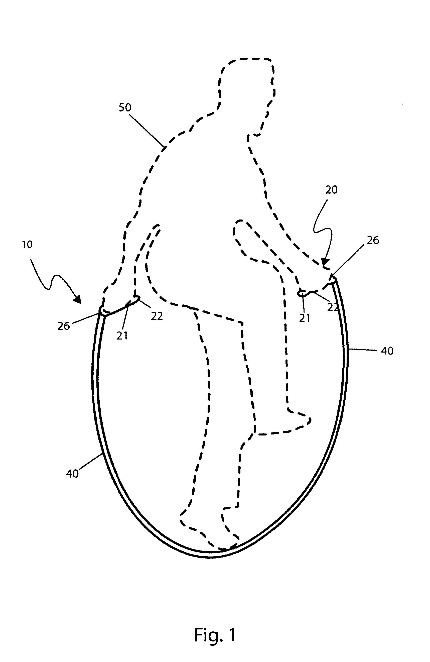
[0031]A method of and utilizing an exercise device comprising a jump rope with resistance hand grips may be achieved by performing the following steps: procuring a particular model of the exercising device which provides a desired jumping rope length and spring resistance; grasping the two (2) grip assemblies such that a user's fingers are in contact with the finger relief portions of the finger grips; squeezing each thumb and finger grip pair together, thereby enabling the flexing motion of the device and reducing a relative distance between said grips; experiencing a normal rope jumping session in a normal manner; and, enjoying combined benefits of arm strengthening and cardio-vascular workouts afforded a user of the present invention.

Problems solved by technology

This obviously lengthens workout sessions and takes away time from other beneficial routines.
Probably the largest obstacle to many Americans that wish to get into shape is the lack of time to exercise.
Unfortunately, this patent does not appear to disclose a pair of resistance hand grip assemblies mounted to a jump rope using a swivel assembly.
Unfortunately, this design patent does not appear to be similar to the disclosed device herein nor does it appear to possess attachment means to a jump rope.
Unfortunately, this patent does not appear to disclose two (2) resistance handle grips attached by means of a swivel mechanism to a jump rope.
Unfortunately, these design patents do not appear to disclose devices that appear to be similar to the disclosed device, nor do the disclosed patents appear to disclose two (2) resistance hand grips attached to a jump rope by means of a swivel assembly.
Unfortunately, the disclosed patent does not appear to disclose a jump rope with a pair of resistance hand grips located on both ends.
Unfortunately, this patent does not appear to disclose a jumping rope with a pair of resistance hand grip assemblies attached by means of a swivel assembly to permit the grip assemblies to remain stationary while the jump rope is utilized.

Method used


Image

  • Jump rope with resistance hand grips
  • Jump rope with resistance hand grips
  • Jump rope with resistance hand grips

Examples


Embodiment Construction

[0052]The best mode for carrying out the invention is presented in terms of its preferred embodiment, herein depicted within FIGS. 1 through 3. However, the invention is not limited to the described embodiment and a person skilled in the art will appreciate that many other embodiments of the invention are possible without deviating from the basic concept of the invention, and that any such work around will also fall under scope of this invention. It is envisioned that other styles and configurations of the present invention can be easily incorporated into the teachings of the present invention, and only one particular configuration shall be shown and described for purposes of clarity and disclosure and not by way of limitation of scope.

[0053]The terms “a” and “an” herein do not denote a limitation of quantity, but rather denote the presence of at least one of the referenced items.

[0054]The present invention describes a device and method for a jumping rope with resistance hand grips ...


PUM


Abstract

An exercise device which combines the functionality of a jump rope with that of a pair of spring-operated hand-grips is herein disclosed. The device comprises two (2) conventional spring-loaded hand grips at distal ends of the rope. The rope is attached to the top of the hand grips using a ball bearing-type swivel joint that allows the rope to turn freely, even while the hand grips are held stationary. It is envisioned that the grips could be flexed while using said exercise device, held in a closed position for resistance training while jumping rope or used alone without utilizing the jump rope.

Description

RELATED APPLICATIONS[0001]The present invention was first described in official Record of Invention filed on Aug. 20, 2007 and incorporated by reference thereto in this application as if set forth fully herein.FIELD OF THE INVENTION[0002]The invention, as presently disclosed, relates generally to a jump rope exercising device and, more specifically, to a jump rope comprising attached resistance hand grips that combines the functionality of a jump rope with that of a pair of spring-operated handgrips each comprising a swivel joint that allows the rope to turn freely, even while the hand grips are held stationary.BACKGROUND OF THE INVENTION[0003]One favorite tool of many who exercise is the jump rope. Jumping rope is a high impact, high aerobic activity that develops cardiovascular and muscular endurance along with agility, coordination, and muscular strength. It can be done virtually anywhere and with minimal equipment costs. Another low cost, but common, piece of exercise equipment ...

Claims


Application Information

Patent Timeline
Patent Type & Authority Patents(United States)
IPC IPC(8): A63B21/00
CPCA63B5/20A63B21/055A63B23/16A63B2208/0204
Inventor RIVERA, III, NICHOLAS
Owner RIVERA III NICHOLAS
Learn More