Eureka AIR delivers breakthrough ideas for toughest innovation challenges, trusted by R&D personnel around the world.

Staple pocket arrangement for surgical stapler

a stapler and pocket technology, applied in the field of staple pockets, can solve the problems of stalling and buckleing of the stapler legs, sharp internal corners of the pocket, and the inability to use the stapler, so as to minimize tight corners, improve the efficiency of space utilization, and reduce the effect of tight corners

Active Publication Date: 2010-10-19
TYCO HEALTHCARE GRP LP
View PDF8 Cites 1599 Cited by
  • Summary
  • Abstract
  • Description
  • Claims
  • Application Information

AI Technical Summary

Benefits of technology

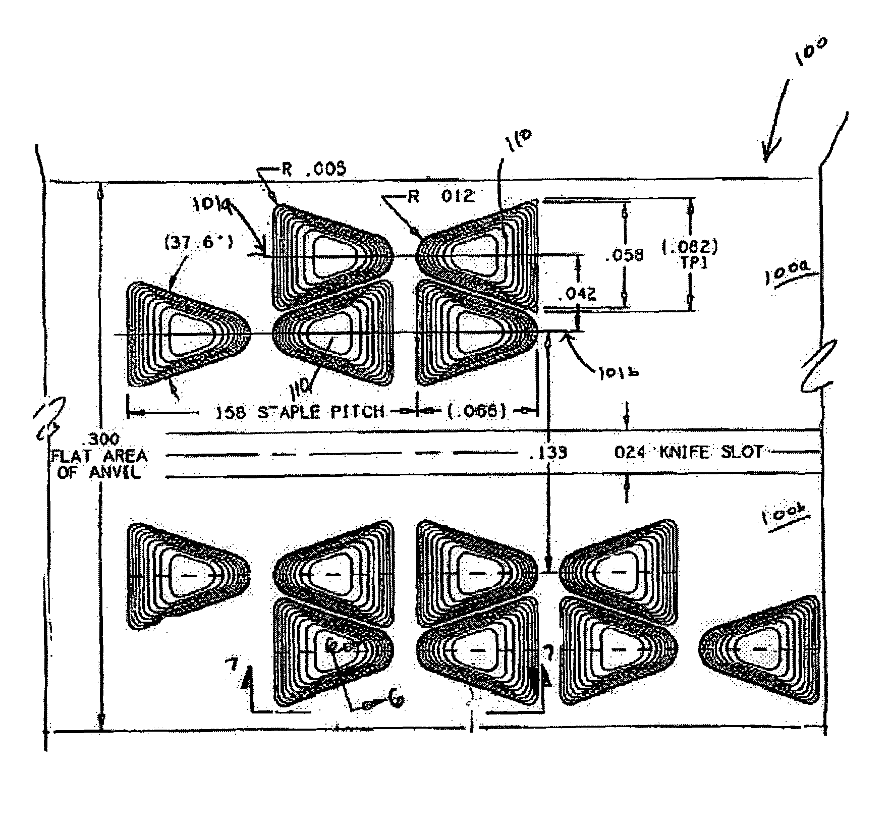
[0009]The staple pockets may have a generally triangular shape when viewed from above. Each respective staple leg is received at a longitudinal end of the staple pocket that provides a relatively wide target area for receiving the staple leg to eliminate or at least minimize the likelihood that a staple leg will miss the staple pocket due to, e.g., misalignment between a first jaw of the surgical stapler having the anvil and a second jaw of the surgical stapler having a cartridge configured to fire the staples. Furthermore, each of the staple pockets is narrower at its opposite end, e.g., the end at which the staple leg emerges after being formed into an arc by the curved canyon floor of the staple pocket. The staple pocket 110 may provide canyon walls, e.g., along which a staple leg is guided, that are steeply angled for the entire wall so that the staple leg travels toward and along the center of the canyon and then up and out the narrow end of the canyon. The floor of the canyon may have a generally smooth and continuous curvature which provides, during bending of the staple leg, sufficiently large radii of curvature so as to eliminate or at least minimize tight corners that may snag or impede staple legs that are moving along the surface.
[0010]Each staple pocket in a first row of staple pockets may be nested with a staple pocket from an adjacent row of staple pockets. In this manner, when each row of staple pockets is longitudinally offset from another row, e.g., by approximately one half of the pocket-pair (or staple) center-to-center pitch, the proximal staple pocket of a first row nests with a distal staple pocket of a second row. The staple pocket arrangement may be more tolerant of poorly aimed staples, may make more efficient use of space on the anvil and may be less likely to cause a staple jam or buckling of the staple leg.

Problems solved by technology

One problem that may be encountered by conventional surgical staple pocket arrangements is that the staple pockets have sharp internal corners that may contribute to snagging or stalling the staple leg of a staple as the staple leg is progressively moved through the staple pocket.
Another problem that may be encountered by conventional surgical staple pocket arrangements is that the staple pockets have a narrow capture area, such that staples that are slightly mis-aligned relative to the staple pockets may miss the pocket.
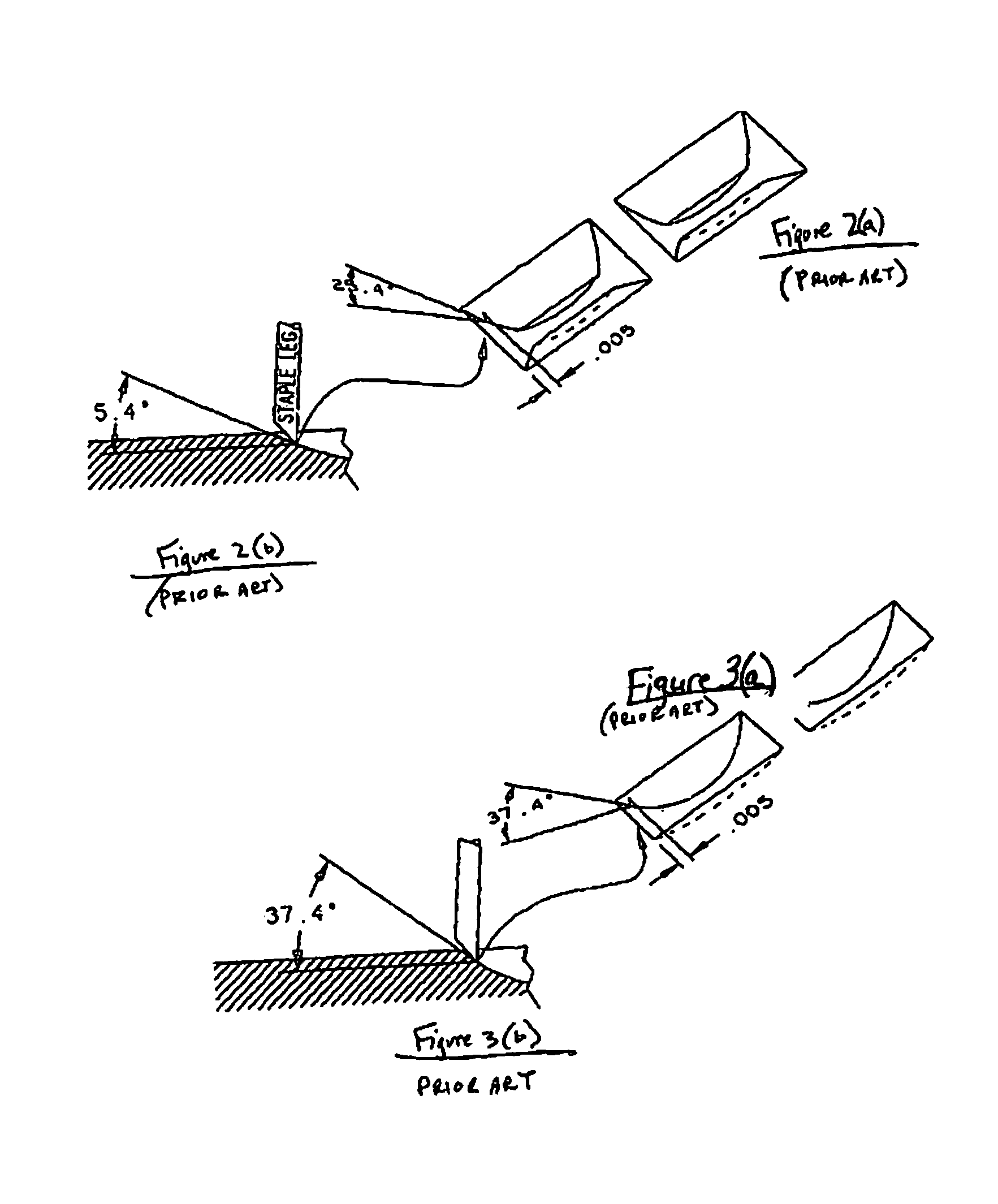
Another problem that may be encountered by conventional surgical staple pocket arrangements is that the staple pockets may have too shallow a slope spread over a broad area so that incoming staple legs do not encounter a sufficiently steep slide angle, thereby causing the staple legs to stall and buckle.

Method used


Image

  • Staple pocket arrangement for surgical stapler
  • Staple pocket arrangement for surgical stapler
  • Staple pocket arrangement for surgical stapler

Examples


Embodiment Construction

[0022]FIG. 5 is a top view of a staple pocket arrangement on the anvil of a surgical stapler, in accordance with an example embodiment of the present invention. Specifically, FIG. 5 illustrates an anvil surface 100 having a first side 100a and a second side 100b separated by a knife slot. On each of the first side 100a and the second side 100b of the anvil surface 100 there is defined two rows of staple pockets 110. Referring to the first side 100a of the anvil surface 100, a first row of staple pockets 110 has a center line 101a and a second row of staple pockets 110 has a center line 101b. For the purposes of clarity, only several staple pockets 110 have been shown. However, the anvil surface 100 may have any number of staple pockets 100 in each of the rows. Furthermore, while exemplary embodiments described herein include rows of staple pockets that are arranged adjacent to a knife slot, exemplary embodiments of the present invention maybe employed in connection with any type of ...


PUM

PropertyMeasurementUnit
slope angleaaaaaaaaaa
widthaaaaaaaaaa

Abstract

A staple pocket arrangement on the anvil portion of a surgical stapler device includes pairs of staple pockets corresponding to each one of a plurality of staples to be closed. The staple pockets may have a generally triangular shape when viewed from above. Each respective staple leg is received at a longitudinal end of the staple pocket that provides a relatively wide target area for receiving the staple leg to eliminate or at least minimize the likelihood that a staple leg will miss the staple pocket due to, e.g., misalignment between a first jaw of the surgical stapler having the anvil and a second jaw of the surgical stapler having a cartridge configured to fire the staples. The staple pockets may be arranged in rows, each row of staple pockets being longitudinally offset from another row, such that each staple pocket in a first row of staple pockets is nested with a staple pocket from an adjacent row of staple pockets to make more efficient use of space on the anvil.

Description

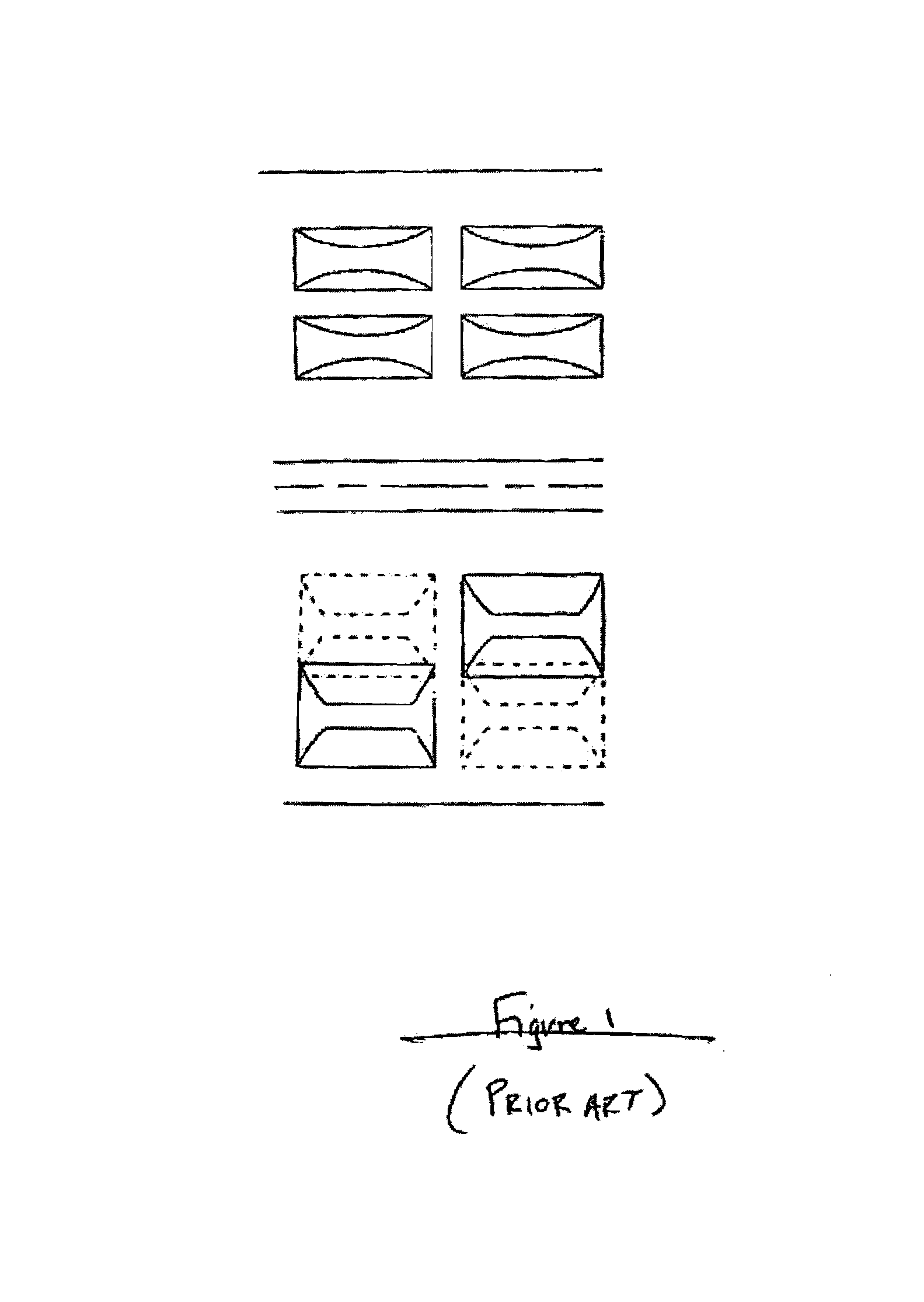
CROSS-REFERENCE TO RELATED APPLICATIONS[0001]This application claims the benefit of U.S. Provisional Patent Application Ser. No. 60 / 703,262, entitled “Staple Pocket Arrangement for Surgical Stapler”, filed Jul. 27, 2005, which is expressly incorporated herein in its entirety by reference thereto.FIELD OF THE INVENTION[0002]The present invention relates to a staple pocket. More specifically, the present invention relates to a staple pocket arrangement for use in a surgical stapler.BACKGROUND INFORMATION[0003]Surgical staplers typically employ an anvil having staple pockets defined therein. Staples are pushed out of a staple cartridge through a section of tissue and against the staple pockets, the staple pockets being shaped so as to receive and progressively bend the legs of the staple into a closed position. FIG. 1 is a top view of a portion of conventional staple pocket arrangements on the anvil of a surgical stapler, e.g., a first arrangement on the upper side of the knife slot an...

Claims


Application Information

Patent Timeline
Patent Type & Authority Patents(United States)
IPC IPC(8): A61B17/068
CPCA61B17/068A61B17/072A61B17/07207A61B17/0684A61B17/0686A61B2017/07228A61B2017/07264
Inventor WHITMAN, MICHAEL P.BURBANK, JOHN E.
Owner TYCO HEALTHCARE GRP LP
Why Eureka
Eureka Blog
Learn More