Foam soap generator

a soap foam and generator technology, applied in the field of soap delivery systems, can solve the problems of system problems, little attention to the specific design or configuration of the constituent elements, and the inability to achieve the desired uniformity and integrity of the resulting foam, and achieve the effect of high quality

Active Publication Date: 2010-10-26
KANFER JOSEPH S
View PDF23 Cites 32 Cited by
  • Summary
  • Abstract
  • Description
  • Claims
  • Application Information

AI Technical Summary

Benefits of technology

[0013]Other aspects of the invention that will become apparent herein are attained by a foam generator for a soap dispenser, comprising: a liquid passage; an air passage converging with said liquid passage at an area of convergence for converging air from said air passage with liquid from said liquid passage; a mixing chamber receiving said converged air and liquid and generating a foam therefrom; and a porous passage at an end of said mixing chamber receiving and finishing said foam as to consistency, uniformity and stability.

Problems solved by technology

Indeed, the prior art foamer heads have typically been of a rudimentary nature, with little regard for the specifics of the design or the configuration of the constituent elements.
While the prior art foamer heads have generally been of a satisfactory nature, little attention has been given to the efficacy of soap foam generation to achieve a desired uniformity and integrity of the resulting foam.
However, such systems have generally proven to be problematic.
It has been found that foam is difficult to drive for any distance through a conduit.
It has also been found that such remote delivery systems have resulted in extremely low output volumes on subsequent dispensing operations, and even total failures to dispense when the period of time between dispensing operations has been sufficient to allow the soap foam within the conduit to fully breakdown.
Other problems have been evidenced with a “wet” foam output on subsequent dispensing operations, resulting from the breakdown of foam in the conduit into a liquid form.
The problems of foam breakdown and suck-back failure are characteristic of such systems.

Method used


Image

  • Foam soap generator
  • Foam soap generator
  • Foam soap generator

Examples


Embodiment Construction

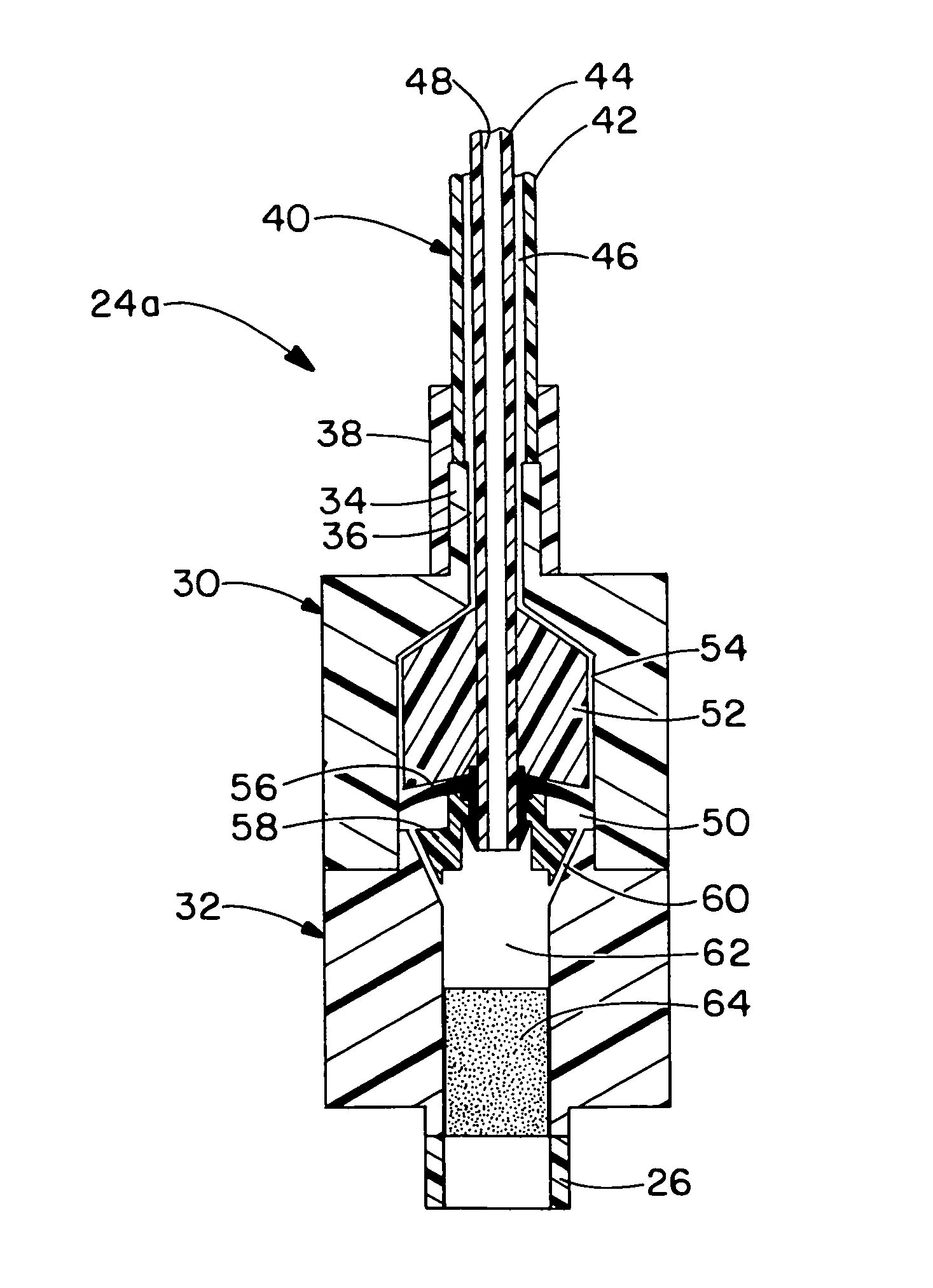
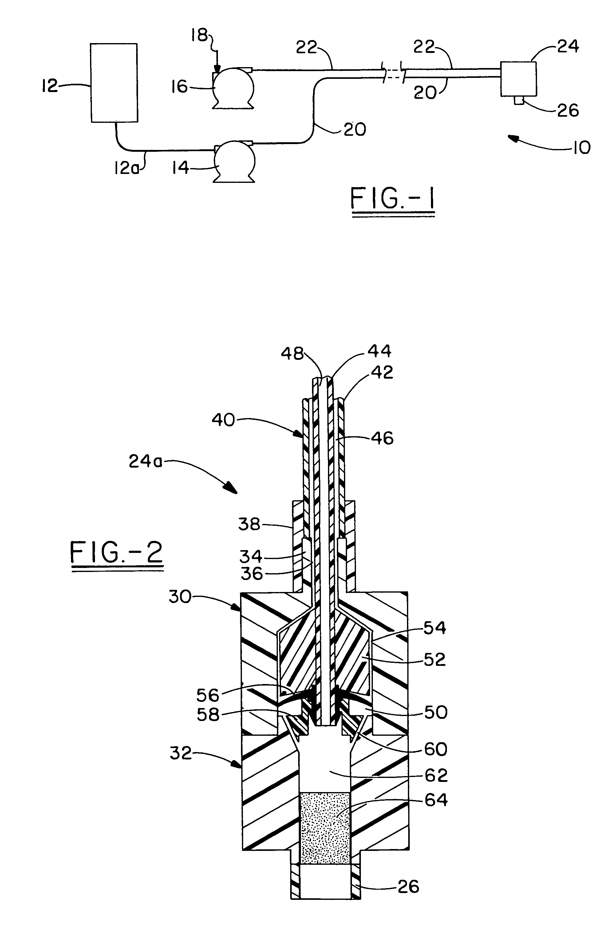
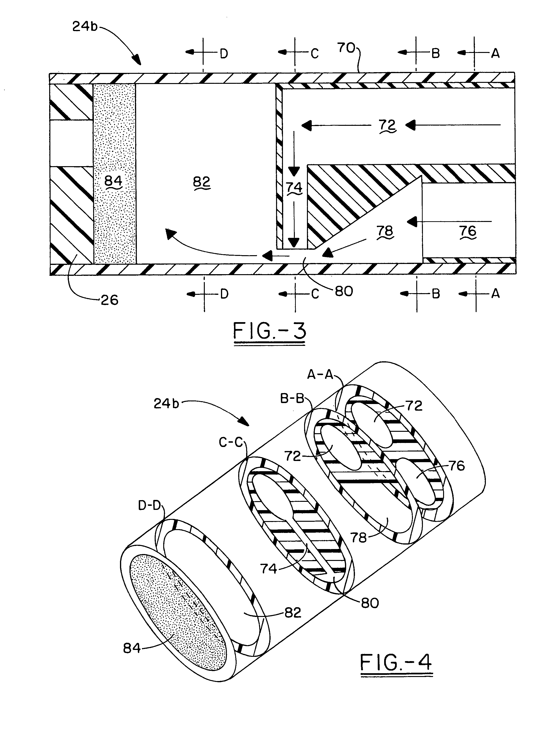
[0019]Referring now to the drawings and more particularly FIG. 1, it can be seen that a soap foam delivery system made in accordance with the invention is designated generally by the numeral 10. It will be appreciated herein that when reference is made to soap, it is intended to extend to lotions, disinfectants and the like. The delivery system 10 includes a source of liquid soap 12 interconnected through a conduit 12a to a liquid soap pump 14. An air pump 16, provided with an air inlet 18, is also provided, it being understood that the ingredients of soap foam are liquid soap and air. The outlet of the liquid soap pump 14 is connected to a liquid flow line 20, with the outlet of the air pump 16 being similarly connected to an air flow line 22. The lines 20, 22 may be totally separate, presented in side by side relation, or coaxial with each other, as will become apparent herein. In any event, the liquid flow line 20 and air flow line 22 are connected to a soap foam generator 24, in...


PUM


Abstract

A foam soap generator is provided for implementation with various types of foam soap delivery systems. The foam soap generator includes converging air and liquid soap passages at a mixing chamber, where a prefoam is generated for ultimate extrusion through a porous passage member. In one embodiment of the invention, the soap and air are delivered through coaxial tubes, with the soap being introduced axially into the mixing chamber and the air being introduced radially angularly. In another embodiment, the liquid soap is drawn into an entrainment zone by high velocity air passing through the air passageway and into the mixing chamber.

Description

TECHNICAL FIELD[0001]The invention herein resides in the art of delivery systems and, more particularly, to soap delivery systems of the type typically employed for hand hygiene. More specifically, the invention relates to a soap foam generator adaptable for use in various types of delivery systems and particularly adapted for generating soap foam at a delivery head remote from a source of liquid soap.BACKGROUND ART[0002]The use of soap dispensers for hand washing has now become widely known and accepted. Typically, such soap dispensers dispense a quantity of soap which is then worked into a lather by the user when combined with water on the hands. Recently, there has been a general acceptance of foam soap delivery systems. In such systems, liquid soap is combined with air, typically under force or pressure, and then driven through a mesh, screen or porous passage to finish or homogenize the soap into a uniform stable composition. In some systems, a mixing chamber is employed prior ...

Claims


Application Information

Patent Timeline
Patent Type & Authority Patents(United States)
IPC IPC(8): B67D7/78B67D7/76
CPCA47K5/14B05B7/0037B05B7/0475B05B7/0483B05B7/0491
Inventor WILLIS, DANIEL M.
Owner KANFER JOSEPH S
Why Eureka
Try Eureka