Article display tray provided with movement guide device, and movement guide device

a technology of movement guide device and display tray, which is applied in the field of display tray, can solve problems such as inefficient operation

Inactive Publication Date: 2010-11-02
SYST COMM CO LTD
View PDF13 Cites 28 Cited by
  • Summary
  • Abstract
  • Description
  • Claims
  • Application Information

AI Technical Summary

Benefits of technology

[0010]In addition, a movement guide device which is installed at a rear-end communication portion of the article display tray according to the present invention is characterized in that the movement guide device includes: a pair of left-right storage chambers and the rear-end communication portion which communicatively connects rear end portions of the pair of left-right storage chambers to each other, cylindrical articles that are circular in cross section being movable between the pair of left-right storage chambers through the rear-end communication portion, wherein the movement guide device includes: a rocking member capable of rocking about a rocking shaft extending in a vertical direction; a pair of force-applied portions provided at left and right ends of the rocking member and positioned on extension lines of the pair of left-right storage chambers, respectively; and an arraying guide surface formed between the pair of force-applied portions. When one of the pair of force-applied portions is pushed rearward by one of the cylindrical articles which is placed in one of the pair of left-right storage chambers, and the other of the pair of force-applied portions pushes another of the cylindrical articles forward which is placed in the other of the pair of left-right storage chambers. Upon the one of the cylindrical articles pushing the one of the force-applied portions rearward so as to come into engagement with the arraying guide surface, the arraying guide surface returns the rocking member to a neutral position where the pair of left-right storage chambers are aligned in a leftward / rightward direction.

Problems solved by technology

In addition, if FILO is done in chilled (refrigerated) articles, a problem arises with well-chilled articles that are displayed for a long time sitting at the back of the display tray, whereas not-yet-chilled articles that are not yet chilled because they have just been restocked remain at the front of the display tray.
To resolve this kind of problem, each time the display tray is restocked with articles, it is necessary to take time to move the already-restocked articles to the front of the display tray and move new articles into the rear of the display tray, which is an inefficient operation.

Method used


Image

  • Article display tray provided with movement guide device, and movement guide device
  • Article display tray provided with movement guide device, and movement guide device
  • Article display tray provided with movement guide device, and movement guide device

Examples


first embodiment

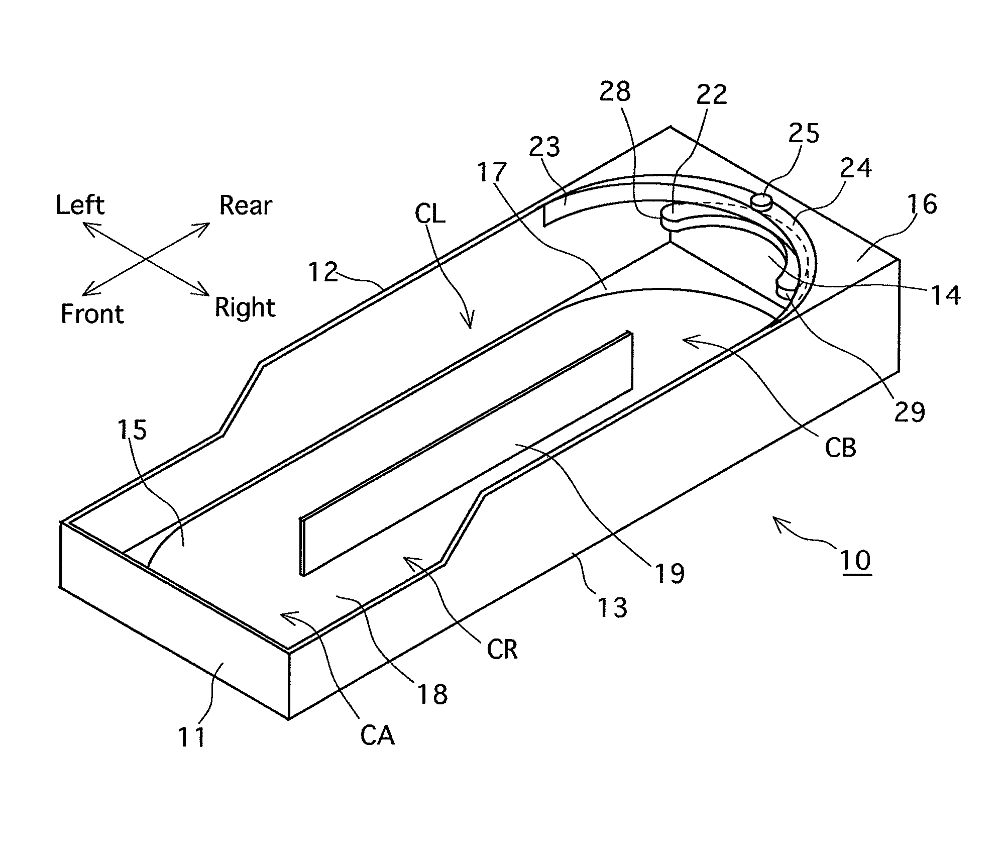
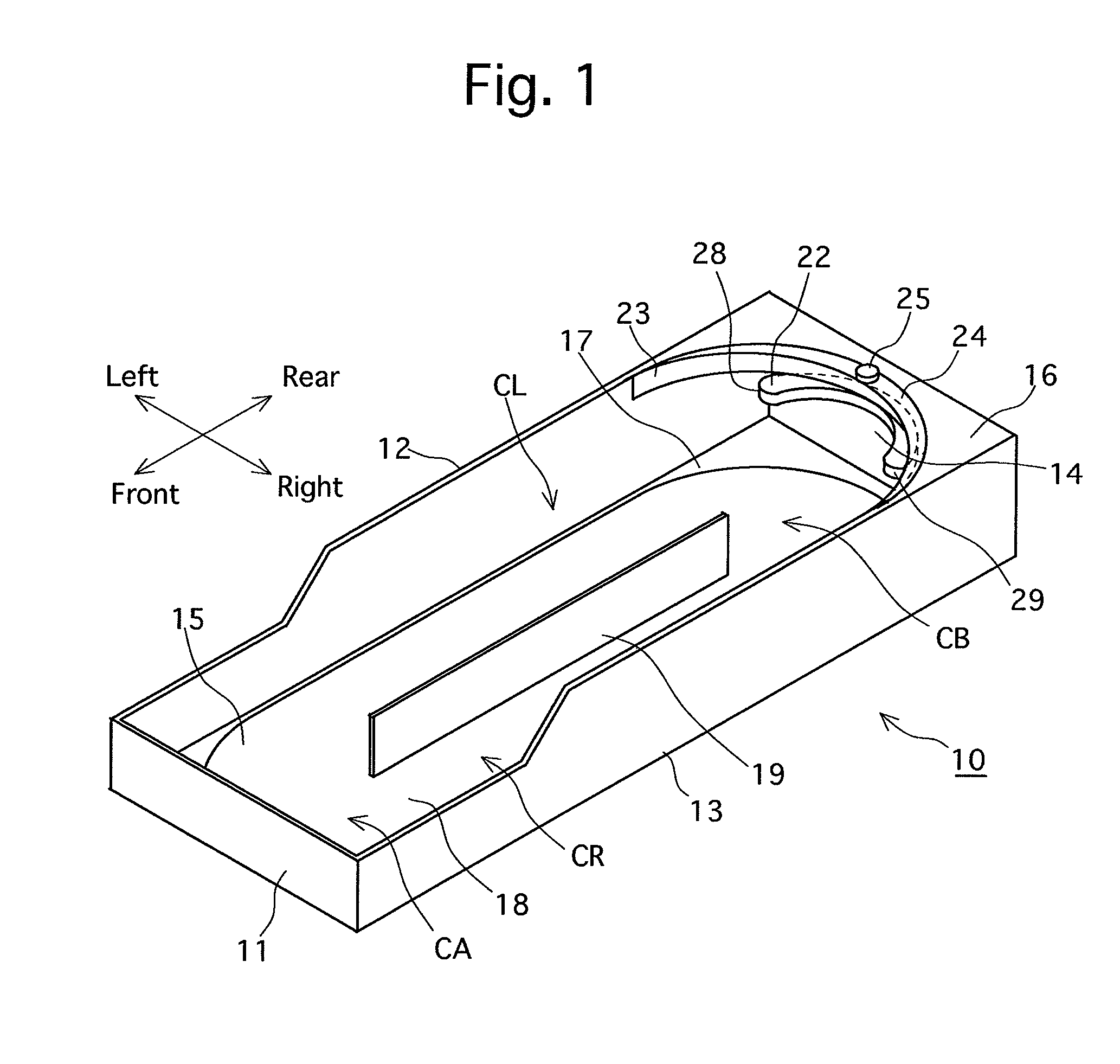
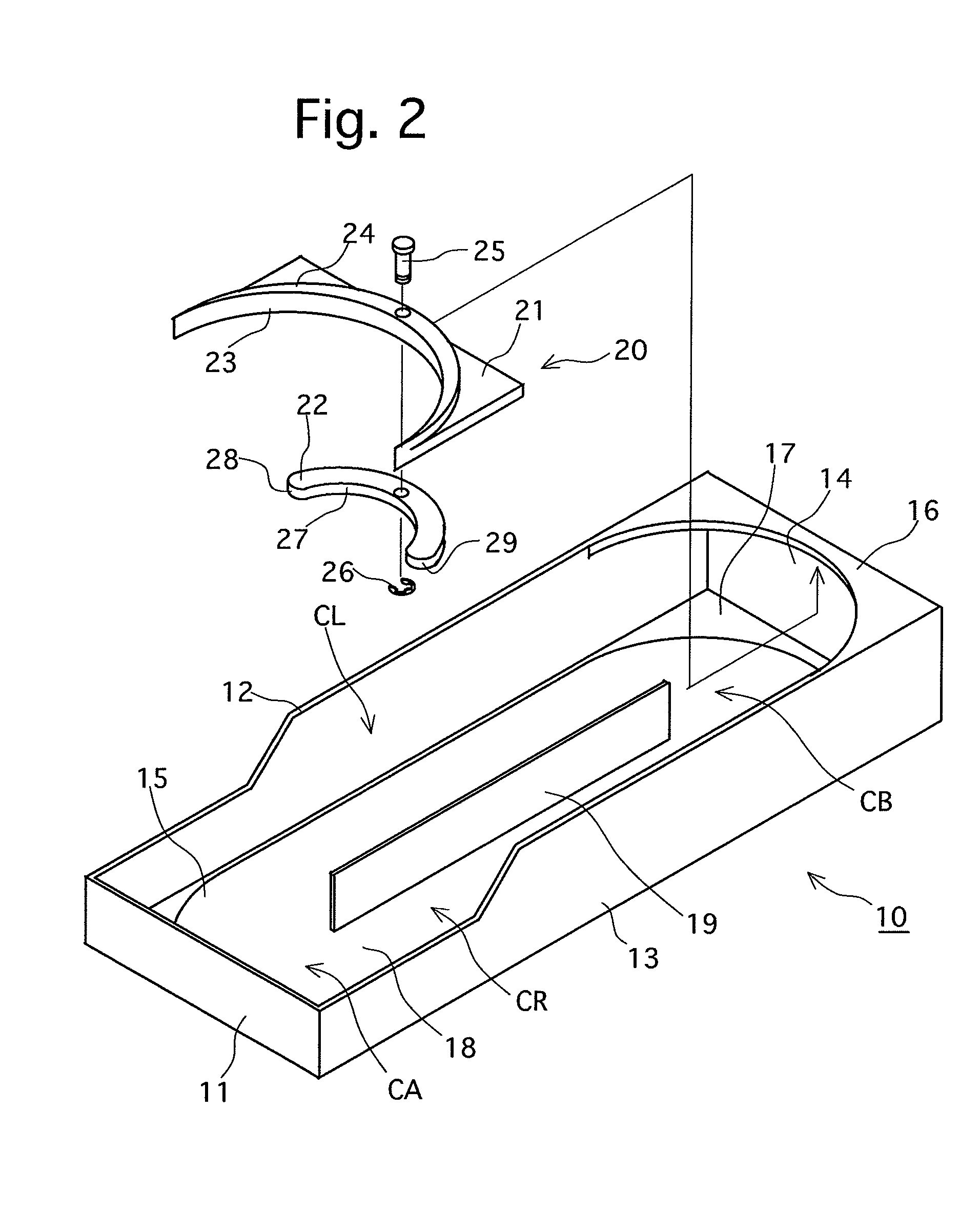
[0035]Firstly, the first embodiment will be hereinafter discussed with reference to FIGS. 1 through 11. Note that the forward / rearward direction and the leftward / rightward direction in the following descriptions shall be the directions shown by the arrows shown in FIG. 1.

[0036]A box-shaped article display tray 10 having an opening at the top is, e.g., fixed to the inside of a refrigeration case, not shown in the drawings, and is integrally provided with a front plate 11, a left-side plate 12, a right-side plate 13, a rear plate 14, a bottom plate 15, and a rear top plate 16, the front surface of which is in the shape of a substantially circular arc. The rear end of the bottom plate 15 is in the shape of a semicircle, and a gap 17 is formed between the rear end portion of the bottom plate 15 and the bottom end portion of the rear plate 14. The bottom plate 15 is further provided with an article mount surface 18 which is shaped like a rectangle, at which two semicircles are formed at ...

second embodiment

[0054]The movement guide device 50 of the second embodiment is provided with a rocking member 51 which is in a shape of a substantially circular arc in plan view, a connecting portion 52 which projects from a central portion of the rear surface of the rocking member 51, and a pivot portion (rocking shaft) 53 in the shape of a half-column which is connected to the rear end of the connecting portion 52. The vertical size of the pivot portion 53 is smaller than the portion between the bottom end surfaces of the retainer plates 40 and 41 and the bottom plate 15. An arraying guide surface 55 is formed on the front surface of the rocking member 51, and the left end surface and the right end surface of the rocking member 51 are formed as a pressed surface (force-applied portion) 56 and a pressing surface (force-applied portion) 57, respectively, each of which is shaped into a curved surface. Additionally, an engaging projection 59 in the shape of a halved circular cone is formed to project...


PUM


Abstract

An article display tray is provided with a movement guide device, wherein cylindrical articles can move more smoothly in a communication portion of the article display tray, via which the pair of storage chambers are communicatively connected to each other, and further wherein an increase in size of the article display tray can be avoided. A pair of left-right force-applied portions and an arraying guide surface positioned between the pair of force-applied portions are formed on a rocking member positioned inside the rear-end communication portion of an article display tray. When one of the pair of force-applied portions is pushed rearward by a cylindrical article that is placed in one of a pair of left-right storage chambers, the other force-applied portion pushes forward a cylindrical article that is placed in the other storage chamber. When the aforementioned one cylindrical article that pushes the aforementioned one force-applied portion rearward comes into engagement with the arraying guide surface after pushing the aforementioned one force-applied portion rearward, the arraying guide surface returns the rocking member to a neutral position where the pair of left-right storage rooms are aligned in a leftward / rightward direction.

Description

FIELD OF THE INVENTION[0001]The present invention relates a display tray, equipped with a movement guide device, for displaying articles, commodities or goods which are cylindrical in cross section (e.g., cans or bottles), and further relates to a movement guide device.BACKGROUND OF THE INVENTION[0002]In an open-case type display tray for displaying cylindrical articles such as cans or bottles, the display tray is restocked with articles from the open front of the display tray because of its structure. Meanwhile, the seller has a demand for reliably selling articles in the lot first restocked (known as FIFO (first in, first out)), i.e., old articles, in consideration of the best-before date (sell-by date) and the impression of consumers. However, in an open-case type display tray, which is restocked with articles from the open front of the display tray, the already-restocked and displayed articles are pushed into the back of the display tray if the display tray is restocked with new...

Claims


Application Information

Patent Timeline
Patent Type & Authority Patents(United States)
IPC IPC(8): A47F7/00
CPCA47F1/087A47F1/12A47F3/14A47F7/28
Inventor FUTORI, MINORU
Owner SYST COMM CO LTD
Why Eureka
Try Eureka