Battery charger

a battery charger and battery technology, applied in the field of battery chargers, can solve the problems of robot shaking, difficulty in connecting the power receiving connector provided in the base body of the robot to the power feeding connector fixed to the battery charger,

a battery charger and battery technology, applied in the field of battery chargers, can solve the problems of robot shaking, difficulty in connecting the power receiving connector provided in the base body of the robot to the power feeding connector fixed to the battery charger,

US7825633B2Inactive Publication Date: 2010-11-02HONDA MOTOR CO LTD

Image

  • Battery charger
  • Battery charger
  • Battery charger

Examples


Embodiment Construction

[0026]The following description of preferred embodiments with reference to the accompanying drawings describes a battery charger of the present invention.

[0027]FIG. 1 to FIG. 5 are descriptive drawings of the configuration of a battery charger of the present invention, and FIGS. 6 and 7 are descriptive drawings of the function of the battery charger of the present invention.

[0028]First, the configuration of the battery charger will be described with reference to the FIG. 1 to FIG. 5.

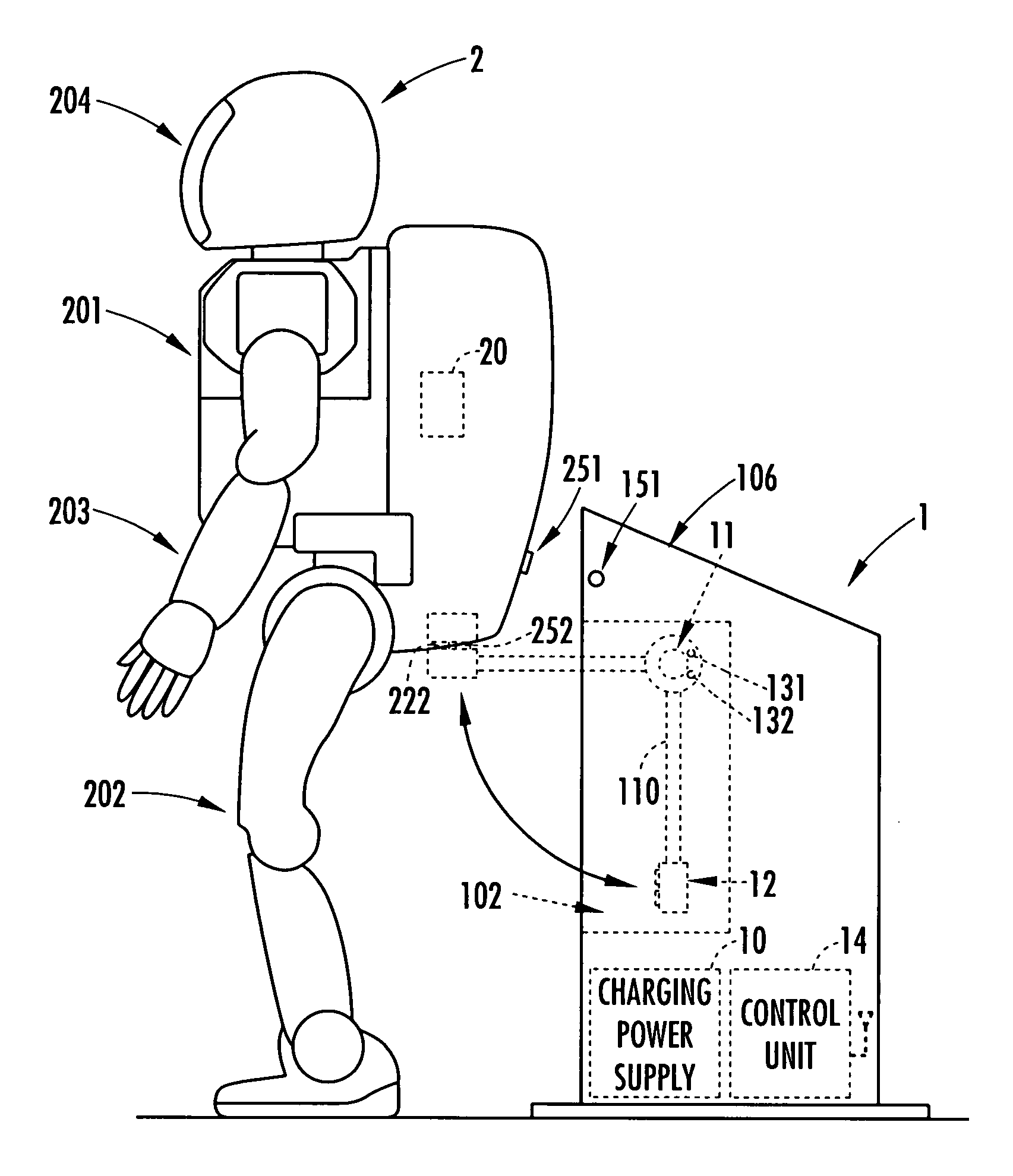
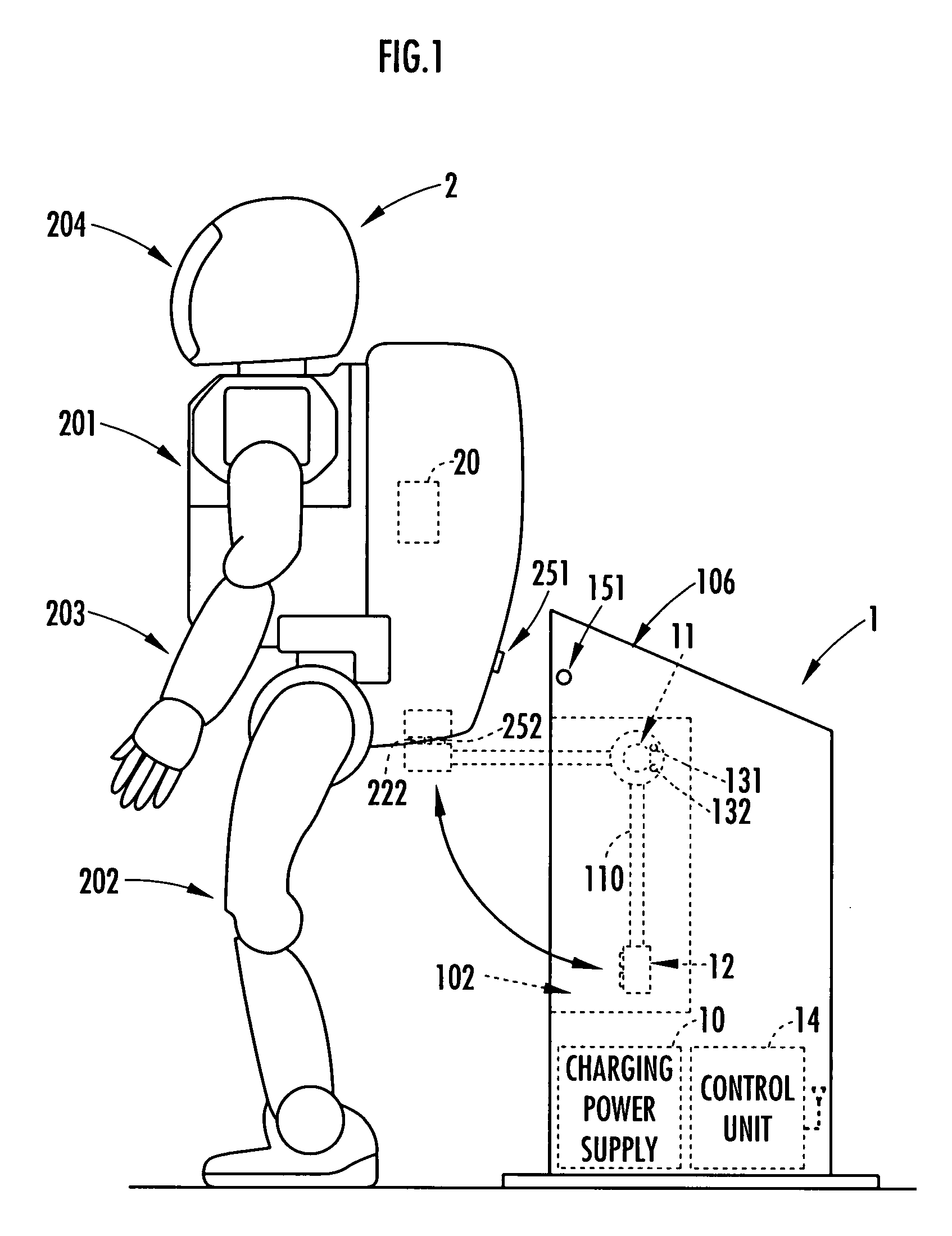
[0029]A battery charger 1 as shown in FIG. 1 has a charging power supply 10 outputting a current for charging a battery 20 mounted aboard a legged moving robot 2, a power feeding connector 12 connected to a power receiving connector 22 disposed at the lower rear part of the robot 2, and a controlling unit (controller) 14.

[0030]The charging power supply 10 includes a voltage transformation circuit to decrease a voltage of the AC power supplied via a plug, a rectification circuit to perform full-wave recti...


PUM


Abstract

An apparatus is capable of charging a battery mounted aboard a robot while avoiding an unstable posture of the robot caused by a power feeding connector coming into contact to a power receiving connector of the robot. A battery charger of the present invention performs control to move the power feeding connecter to connect with the power receiving connector of the robot in a standing posture, so that a moment generated about a target zero moment point (ZMP) of the robot falls within a range of the moment of floor reaction force generatable about the target ZMP.

Description

BACKGROUND OF THE INVENTION[0001]1. Field of the Invention[0002]The present invention relates to a battery charger for charging a battery mounted aboard a legged robot movable by movement of a plurality of legs extending from a base body.[0003]2. Description of the Related Art[0004]As a conventional method for charging a battery mounted aboard a legged moving robot, it has been proposed that, for example, a power receiving connector in a robot and a power feeding connector with a chair in a condition in which the robot sits in the chair be connected to charge the battery via the connectors (for example in Japanese Patent Laid-Open Publication No. 2001-179663).[0005]Because the space occupied by the chair is relatively large, however, the battery charger may present an obstacle to a walker at times other than when charging the robot with power. After charging the robot, because the robot must stand up from the chair, the starting time of the robot to move is delayed. In light of thes...

Claims


Application Information

Patent Timeline
02 Nov 2010
Publication
US7825633B2
IPC
H02J7/00; B25J5/00
CPC
H02J7/0045
Inventors
UDONO, KENRO