Tool holder sleeve

a tool holder and sleeve technology, applied in the field of tool holder sleeve, can solve problems such as wear on attack tools

Active Publication Date: 2010-11-16
SCHLUMBERGER TECH CORP
View PDF115 Cites 55 Cited by
  • Summary
  • Abstract
  • Description
  • Claims
  • Application Information

AI Technical Summary

Benefits of technology

[0007]The sleeve may have a shoulder portion adapted to abut a base of a carbide bolster or an enlarged portion of the shank of the tool. A underside of the shoulder portion of the sleeve may be tapered. The shoulder may also comprise a gripping feature along its outer diameter such as a non-circular geometry, a pinhole, a notch, or combinations thereof. The shoulder portion may also have a stabilizing feature such as an annular groove which is adapted to fit within an annular protrusion of the base or enlarged portion which may radially stabilize the carbide bolster while still allowing rotation.

Problems solved by technology

Formation degradation, such as asphalt milling, mining, or excavating, may result in wear on attack tools.

Method used


Image

  • Tool holder sleeve
  • Tool holder sleeve
  • Tool holder sleeve

Examples


Embodiment Construction

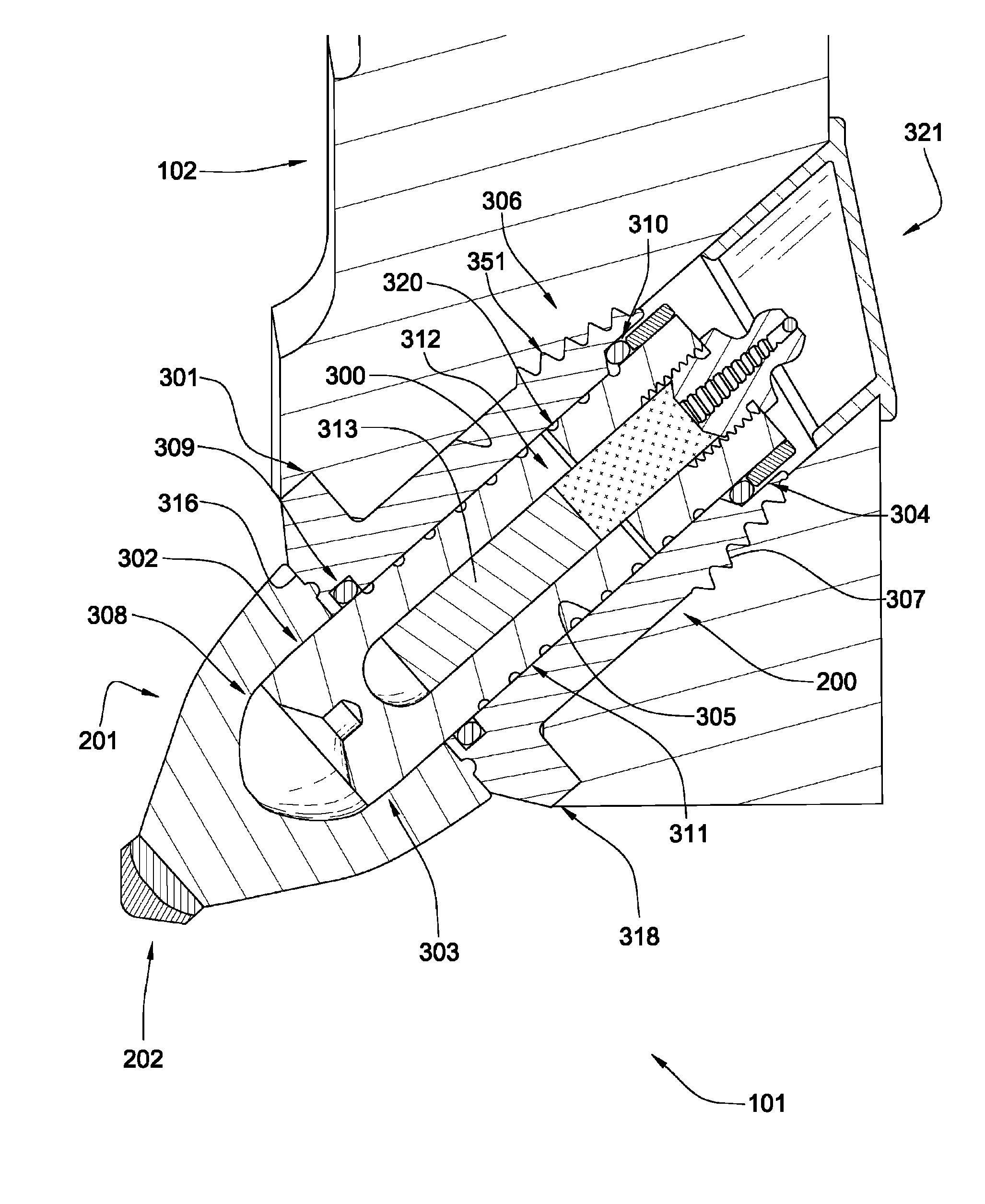
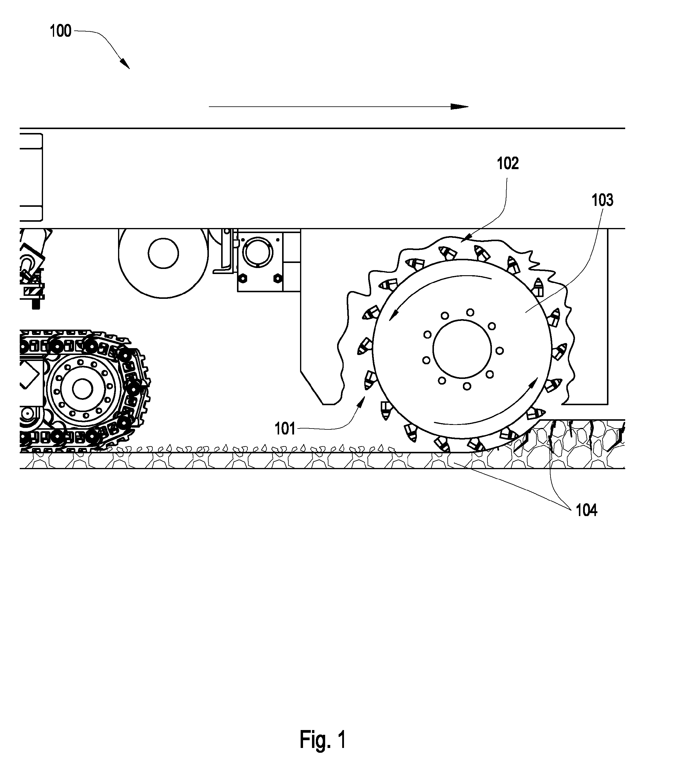
[0019]FIG. 1 is a cross-sectional diagram of an embodiment of a plurality of tools 101 attached to a rotating drum 103 connected to the underside of a pavement recycling machine 100. The recycling machine 100 may be a cold planer used to degrade man-made formations 104 such as pavement. Tools 101 may be inserted into a sleeve, the sleeve being fit within a holder 102. The holder 102 being fit within a block that is attached to the rotating drum 103. The holder 102 may hold the sleeve, and thereby the tool, at an angle offset from the direction of rotation, such that the tool 101 engages the pavement at a preferential angle. The tool 101 may be rotationally fixed to the rotating drum 103.

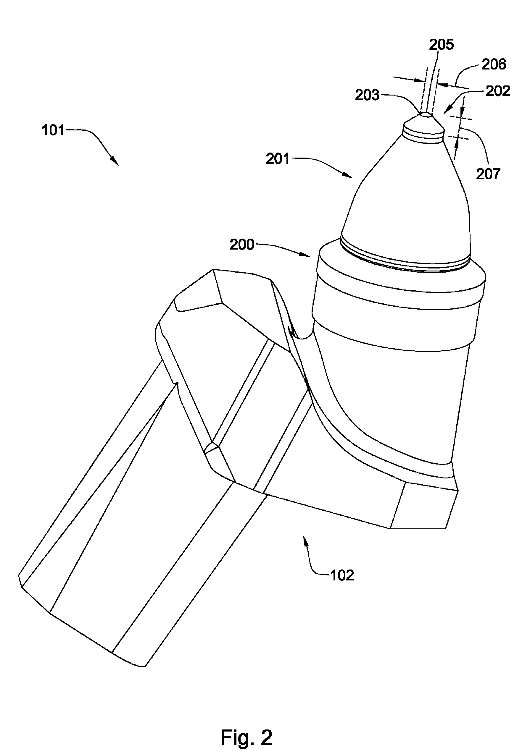
[0020]FIG. 2 illustrates an embodiment of a tool 101 disposed in a sleeve 200. The sleeve 200 is inserted into a holder 102. The high impact resistant tool 101 comprises a carbide bolster 201 intermediate a steel shank and an impact tip 202; the steel shank being inserted into the sleeve 200. The imp...


PUM


Abstract

In one aspect of the present invention, a degradation assembly has a holder fitted within a block attached to a driving mechanism. The holder has a longitudinal central bore with an opening at an end opposite the driving mechanism. A high impact resistant tool has a carbide bolster axially intermediate a steel shank and an impact tip, the steel shank having a first end and a second end. A sleeve being radially intermediate the bore of the holder and the steel shank.

Description

BACKGROUND OF THE INVENTION[0001]Formation degradation, such as asphalt milling, mining, or excavating, may result in wear on attack tools. Consequently, many efforts have been made to efficiently remove and replace these tools.[0002]U.S. Pat. No. 6,371,567 to Sollami, which is herein incorporated by reference for all that it contains, discloses a bit holder with its mating bit block utilizing a slight taper in the bit block bore, and a tapered shank on the bit holder that includes a second larger diameter tapered distal segment that combines with an axially oriented slot through the side wall of the bit holder shank to allow a substantially larger interference fit between the distal tapered shank segment and the bit block bore than previously know. When inserting the bit holder in the bit block bore, the distal first tapered segment resiliently collapses to allow insertion of that segment into the bit block bore. A second shank tapered portion axially inwardly of the first distal t...

Claims


Application Information

Patent Timeline
Patent Type & Authority Patents(United States)
IPC IPC(8): E21C35/19
CPCE21C35/197E21C2035/1826E21C35/188
Inventor HALL, DAVID R.CROCKETT, RONALDJEPSON, JEFF
Owner SCHLUMBERGER TECH CORP
Why Eureka
Try Eureka