Oral suction swab

a suction opening and oral technology, applied in the field of oral suction swab, can solve the problems of tissue being bruised, tissue drawn into the suction opening and engaging a rough edge, and the single opening positioned in the distal end is often not properly oriented in order, so as to prevent tissue from being damaged

Inactive Publication Date: 2010-12-07
TRADEMARK MEDICAL
View PDF74 Cites 63 Cited by
  • Summary
  • Abstract
  • Description
  • Claims
  • Application Information

AI Technical Summary

Problems solved by technology

However, a single opening positioned in the distal end is often times not properly orientated in order to efficiently aspirate all oral fluids.
In addition, if full vacuum force is applied to the swab, tissue can be undesirably drawn into the opening.
Any tissue drawn into a suction opening and engaging a rough edge could be bruised.
However, the location of the bend is not properly positioned for all conditions, particularly for patients in intensive care units (ICU).
If the healthcare worker employs a suction tube that is not angled or the angle of the suction tube does not correspond to the angle of the patient's head, the arm of the healthcare worker may be placed at a non-ergonomic angle which could lead to discomfort for the patient, as well as to discomfort or fatigue to the healthcare worker.

Method used


Image

  • Oral suction swab
  • Oral suction swab
  • Oral suction swab

Examples


Embodiment Construction

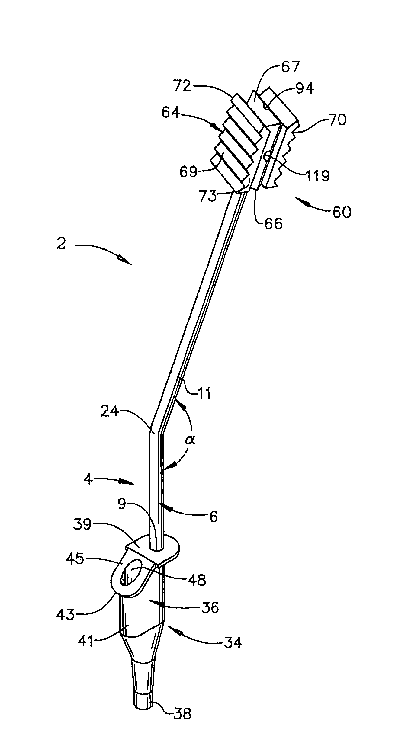
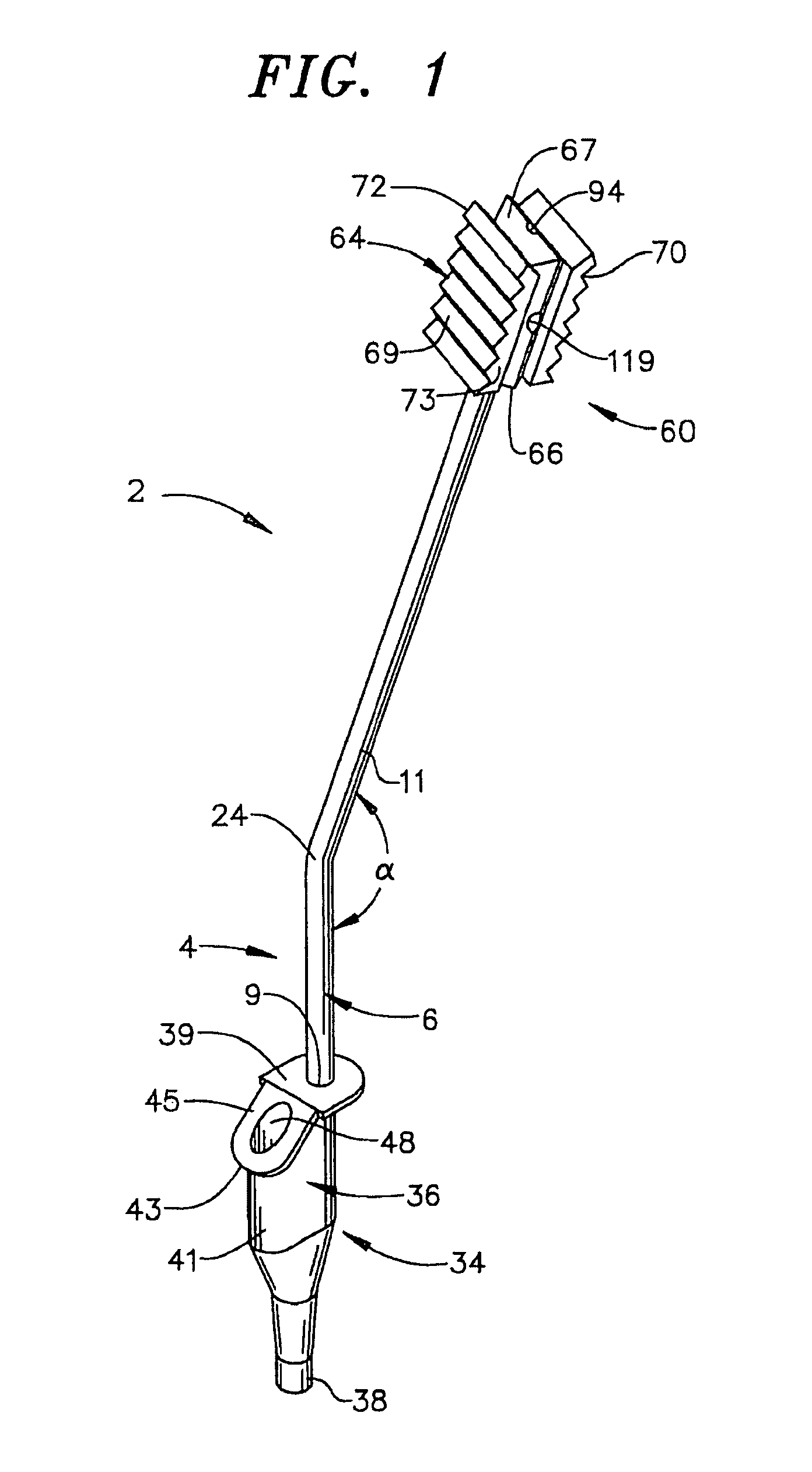
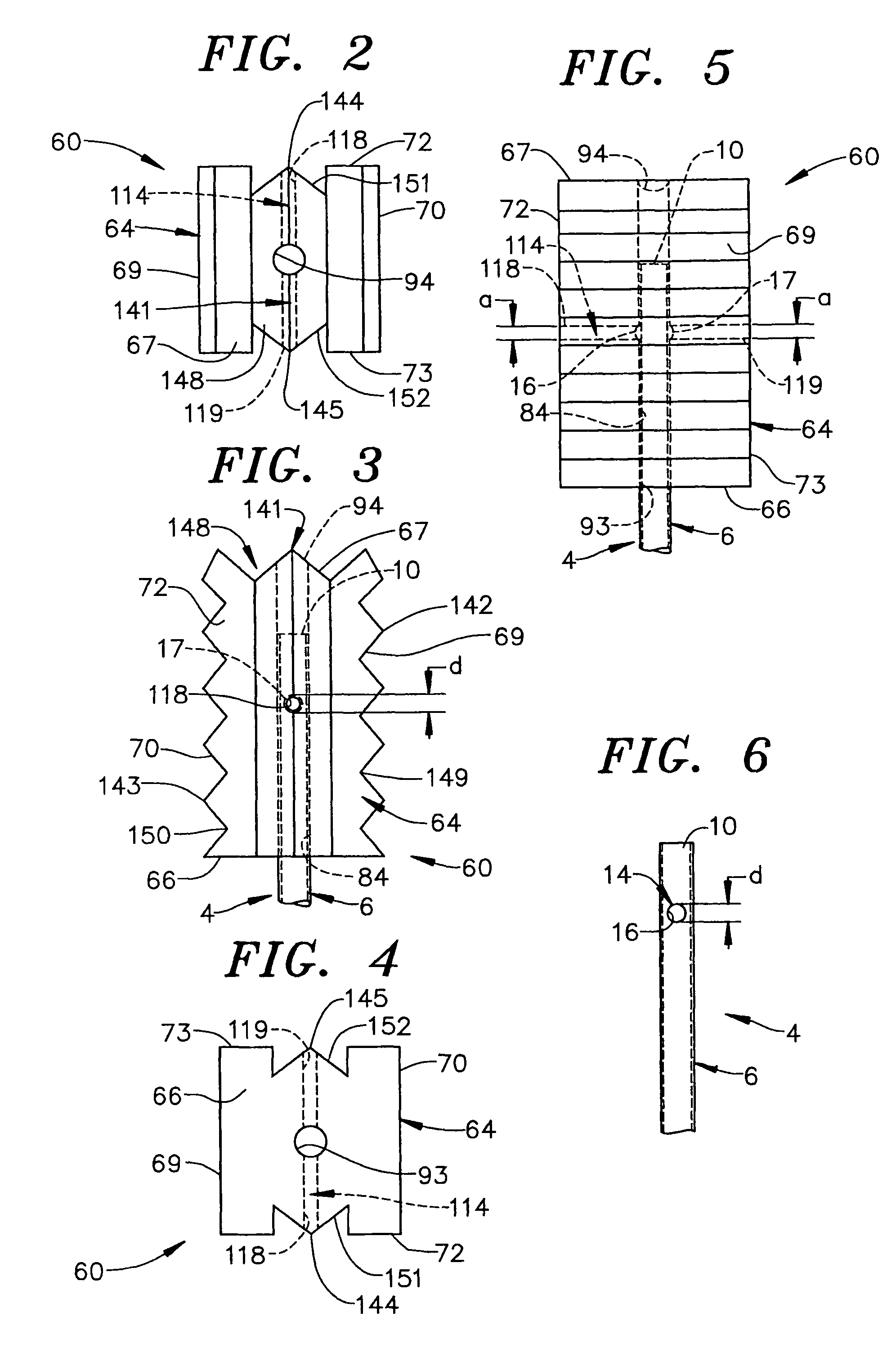
[0018]With initial reference to FIGS. 1 and 6, a suction swab constructed in accordance with the present invention is generally indicated at 2. Suction swab 2 includes a suction tube 4 having an elongated hollow main body 6 provided with first and second end portions 9 and 10 spaced by an intermediate portion 11. Suction tube 4 includes a transverse bore 14 arranged proximate to second end portion 10. Transverse bore 14 defines a first opening 16 having a first diameter (d) that opens or leads into hollow main body 6, and a second opening 17 (see FIGS. 3 and 5) having a second diameter (d) which also leads into hollow main body 6. Suction tube 4 is shown to include a bend portion 24 having an angle (α) which, in accordance with the most preferred form of the invention, is approximately 30°. As will be discussed further below, in accordance with one embodiment of the invention, bend portion 24 is positioned closer to first end portion 9 than to second end portion 10, especially when ...


PUM


Abstract

A suction swab includes a suction tube having a hollow body provided with first and second open end portions and a bend portion. The hollow body includes a transverse bore arranged proximate to the second end which defines first and second openings. The resilient tip includes a main body having a first end section, a second end section and first and second opposing side sections and a central passage. The central passage extends through the main body and is open at each of the first and second end sections so as to define a first aperture arranged at the first end section and a second aperture arranged at the second end section. The resilient tip also includes a transverse passage that extends between one of the first and second opposing side sections and the central passage defining third and fourth openings which are smaller than the first and second openings.

Description

BACKGROUND OF THE INVENTION[0001]1. Field of the Invention[0002]The present invention pertains to the art of oral swabs and, more particularly, to an oral suction swab for aspirating liquid or other material from an oral cavity of a patient.[0003]2. Discussion of the Prior Art[0004]Suction swabs are used to perform oral care on patients who cannot swallow, such as when undergoing a dental procedure or due to some physical impairment or mechanical obstruction. Typically, the swabs are disposable and constructed in various shapes and sizes. A typical swab includes a foam head, a suction tube and a vacuum break. Often times, the foam head will include an opening in a distal end portion that leads into the suction tube to aid in aspirating fluid from an oral cavity. However, a single opening positioned in the distal end is often times not properly orientated in order to efficiently aspirate all oral fluids. In addition, if full vacuum force is applied to the swab, tissue can be undesira...

Claims


Application Information

Patent Timeline
Patent Type & Authority Patents(United States)
IPC IPC(8): A61C17/06
CPCA61C17/043A61C17/08
Inventor DIGASBARRO, PHILLIP PETER
Owner TRADEMARK MEDICAL
Why Eureka
Try Eureka