
Rotary compressor for changing compression capacity
a compression capacity and rotary compressor technology, applied in the direction of positive displacement liquid engine, piston pump, liquid fuel engine, etc., can solve the problem that the conventional rotary compressor cannot have different compression capacities, the rotational speed of the reciprocating compressor is limited, and the vibration is considerable, so as to achieve the compression efficiency with accuracy
- Summary
- Abstract
- Description
- Claims
- Application Information
AI Technical Summary
Benefits of technology
Problems solved by technology
Method used
Image

Examples
Embodiment Construction
[0038]Reference will now be made in detail to the preferred embodiments of the present invention to achieve the objects, with examples of which are illustrated in the accompanying drawings. Wherever possible, the same reference numbers will be used throughout the drawings to refer to the same or like parts.
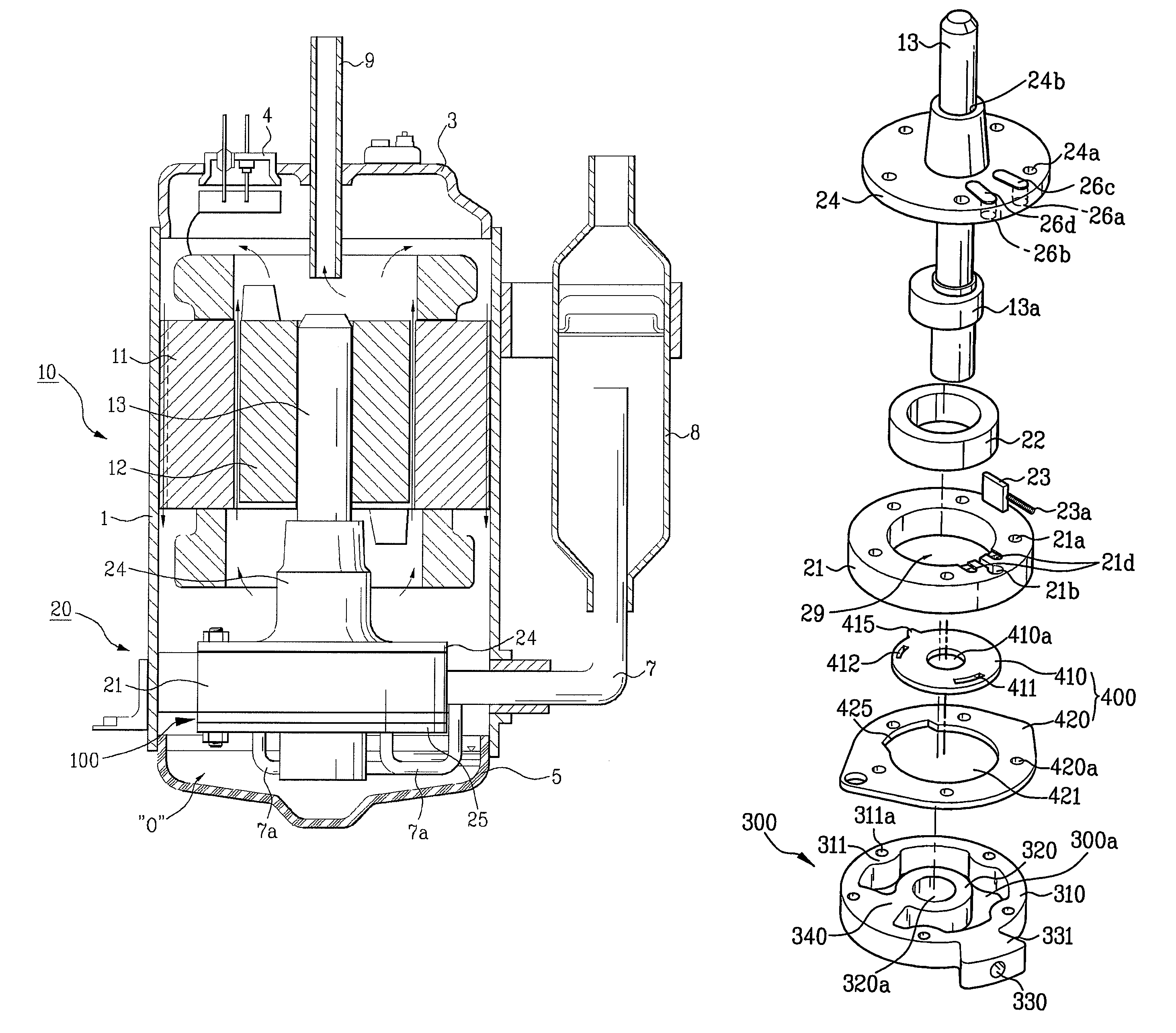
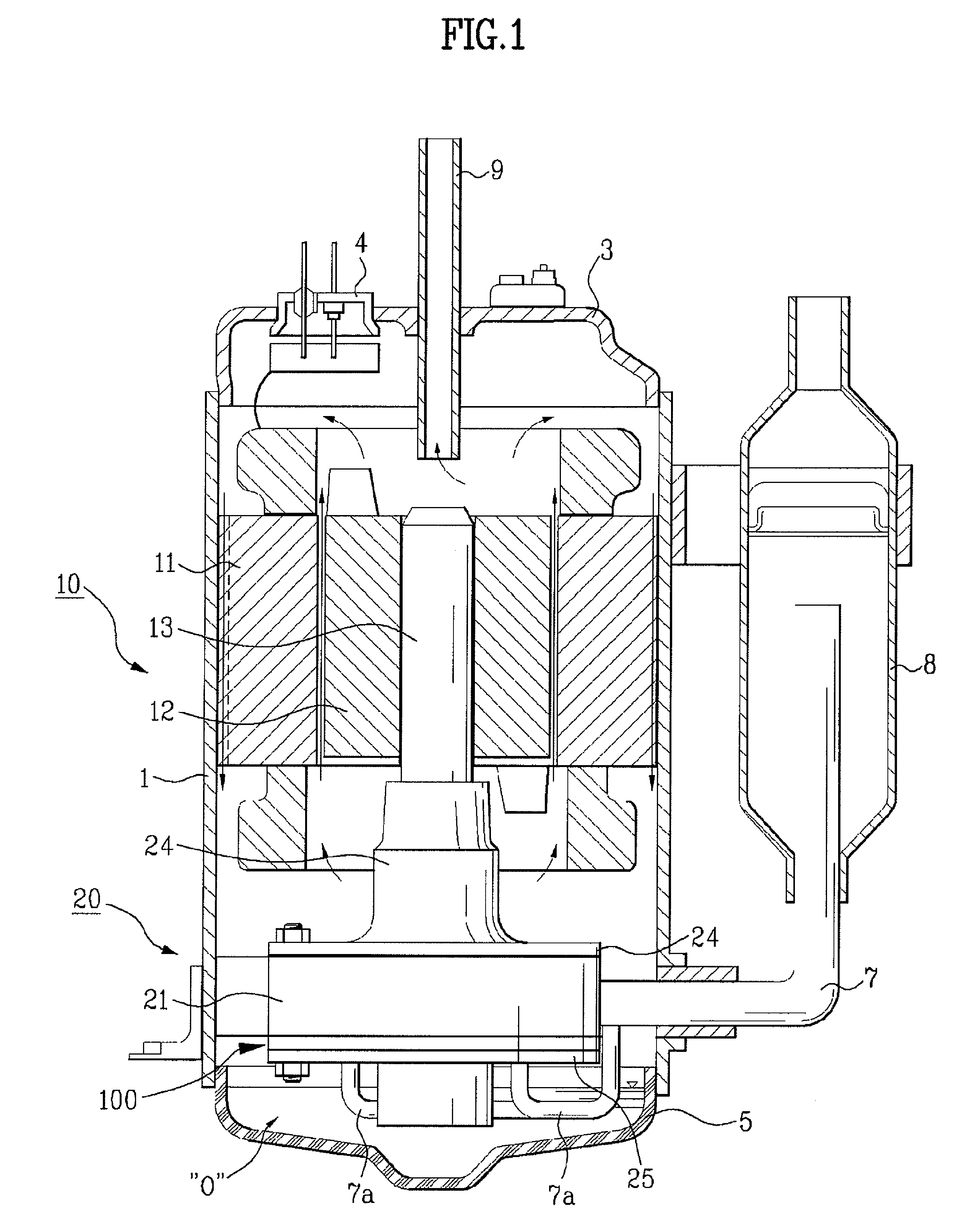
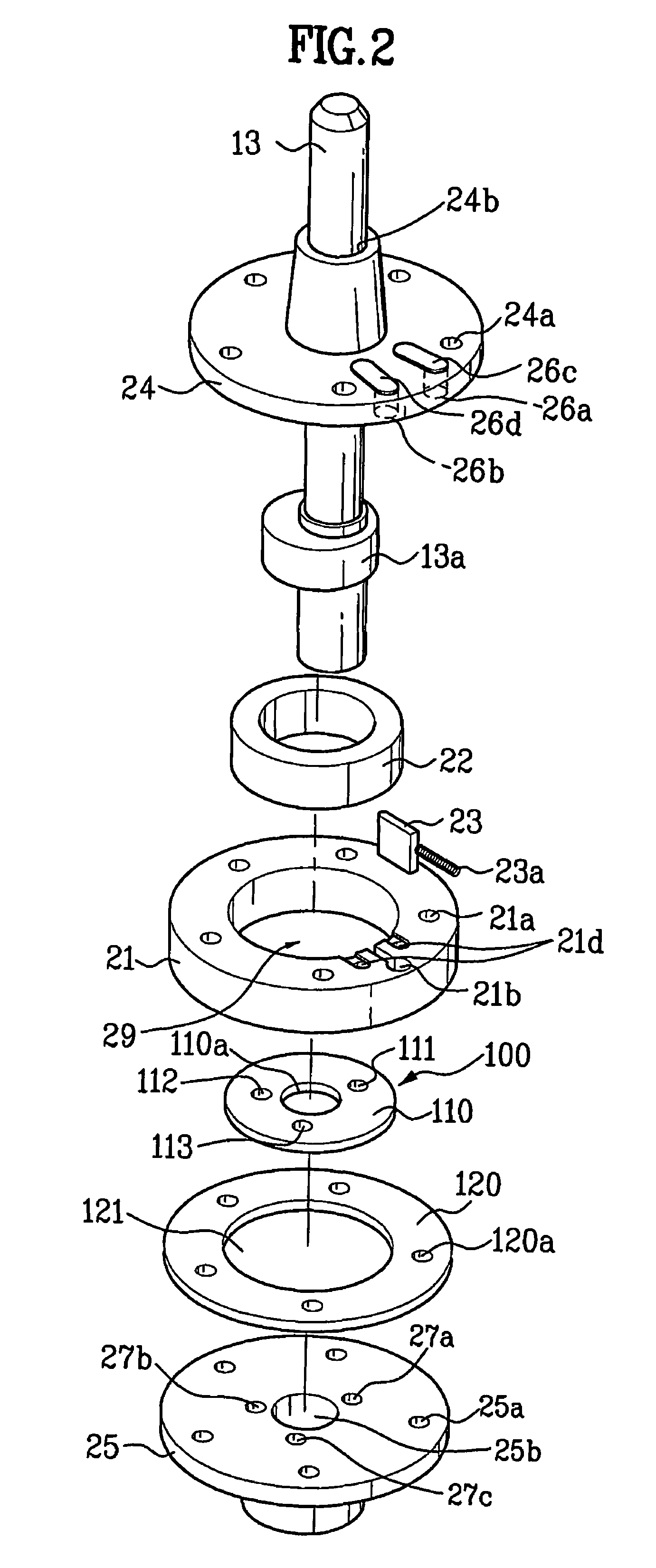
[0039]FIG. 1 is a partial longitudinal sectional view illustrating a rotary compressor according to an embodiment of the present invention, FIG. 2 is an exploded perspective view illustrating that a valve assembly that is not biased eccentrically is installed in the compressing unit of the rotary compressor of FIG. 1, and FIG. 3 is a sectional view illustrating the compressing unit of FIG. 2. An embodiment of the present invention will be described with reference to FIGS. 1 to 3.
[0040]As shown in FIG. 1, a rotary compressor of the present invention includes a case 1, a power generator 10 positioned in the case 1 and a compressing unit 20. Referring to FIG. 1, the power generator 1...
PUM
 Abstract
Description
Claims
Application Information