Holding apparatus for holding optical element above a base, exposure apparatus including the holding apparatus, and device manufacturing method using the exposure apparatus

a technology for holding apparatus and optical elements, applied in the field of holding apparatus for holding optical elements in the exposure apparatus, can solve the problems of small manufacturing errors of flexure members, and achieve the effect of reducing the change in the surface shape of the optical elemen

Inactive Publication Date: 2011-02-01
CANON KK
View PDF19 Cites 12 Cited by
  • Summary
  • Abstract
  • Description
  • Claims
  • Application Information

AI Technical Summary

Benefits of technology

[0011]The present invention is directed to a holding apparatus which holds an optical element with a flexure member and which reduces changes in the surface shape of the optical element caused when the optical element is removed and reattached.

Problems solved by technology

In general, the flexure members have small manufacturing errors.

Method used


Image

  • Holding apparatus for holding optical element above a base, exposure apparatus including the holding apparatus, and device manufacturing method using the exposure apparatus
  • Holding apparatus for holding optical element above a base, exposure apparatus including the holding apparatus, and device manufacturing method using the exposure apparatus
  • Holding apparatus for holding optical element above a base, exposure apparatus including the holding apparatus, and device manufacturing method using the exposure apparatus

Examples


first embodiment

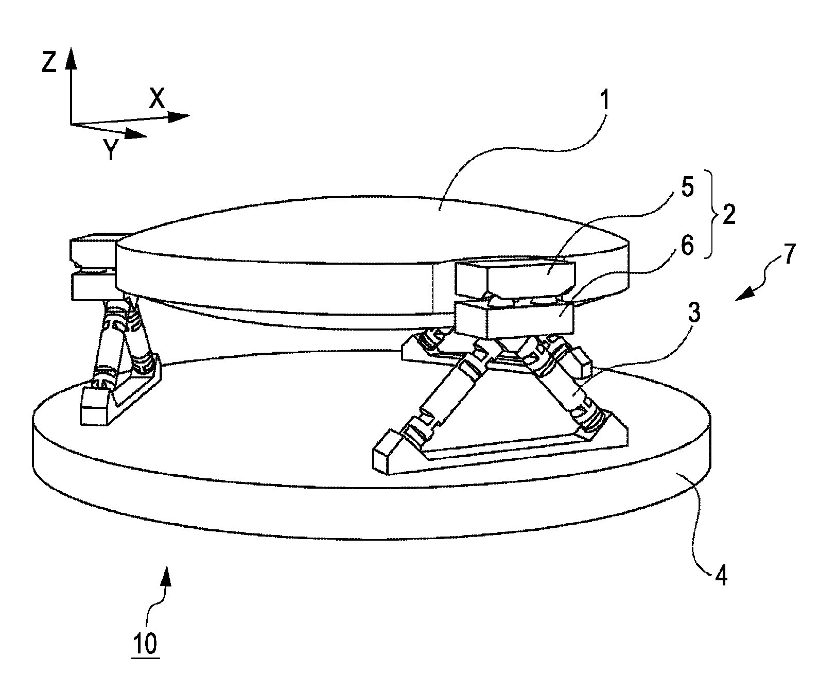
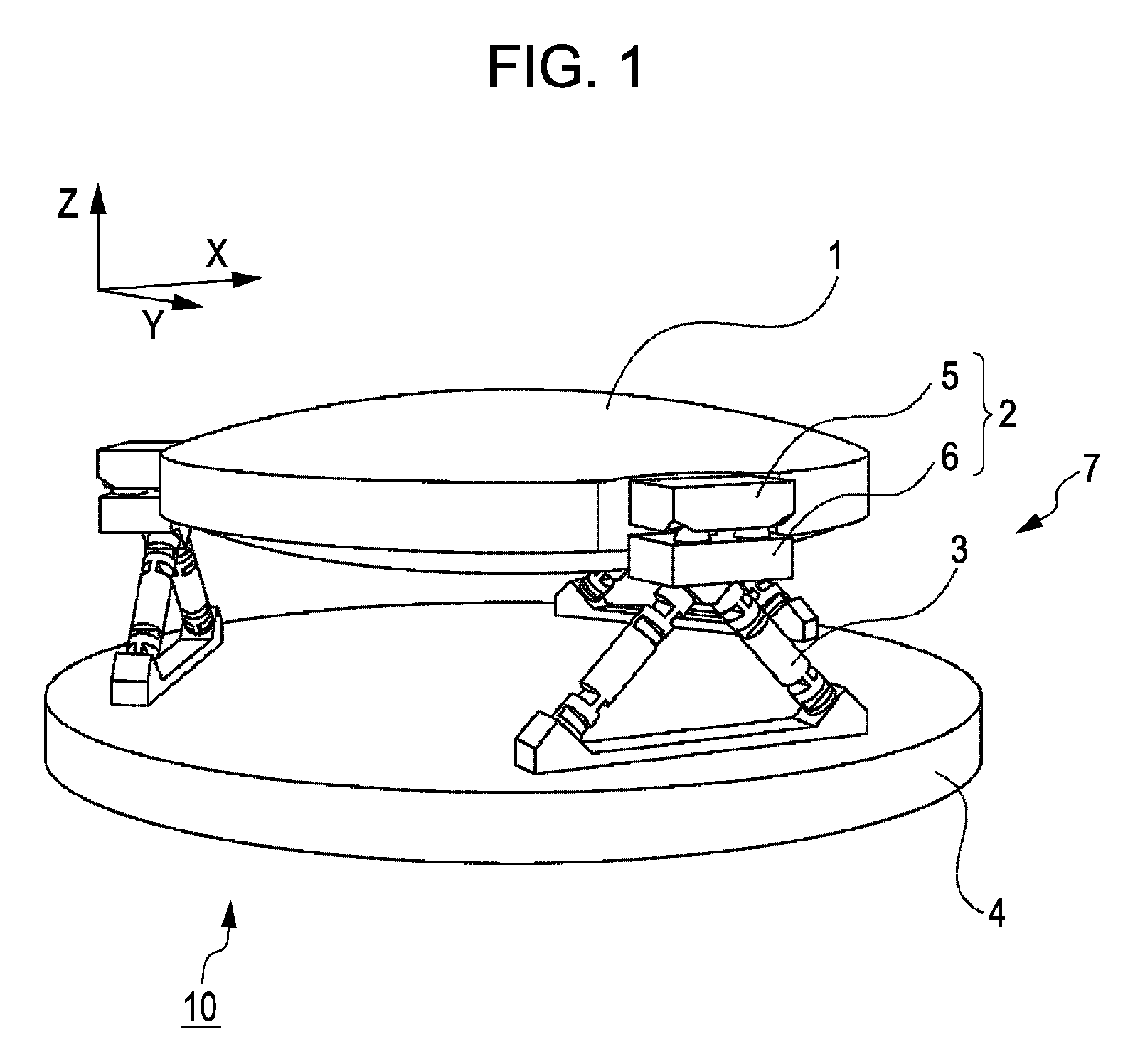
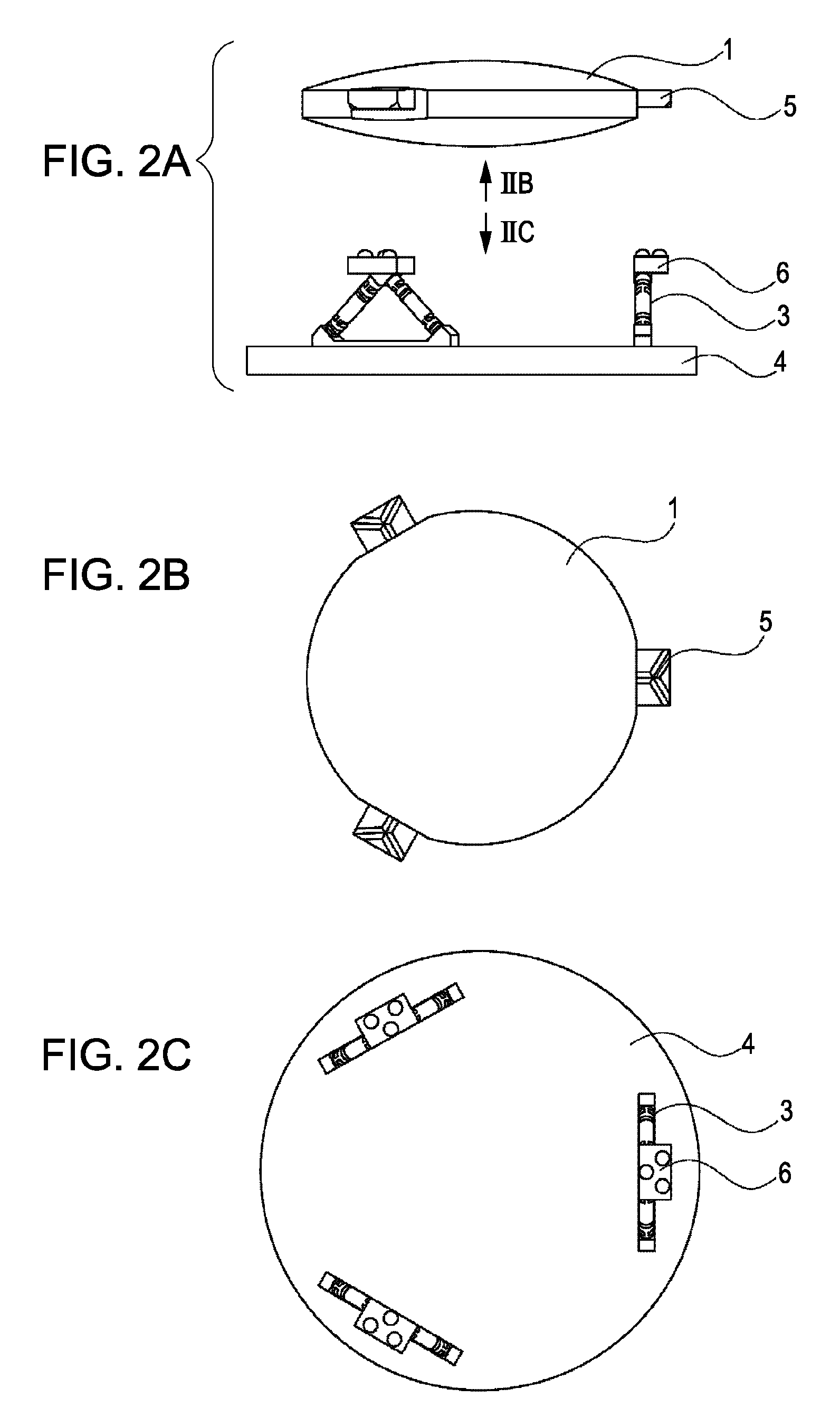
[0037]FIGS. 1 and 2A to 2C illustrate a holding apparatus according to a first embodiment of the present invention. In the figures, a light-axis direction is defined as the Z axis and two perpendicular directions in a plane perpendicular to the Z direction are defined as the X and Y directions. FIG. 1 is a perspective view of the holding apparatus. FIG. 2A is a side view of the holding apparatus in the state in which an object to be held is removed from a base. FIG. 2B illustrates the structure viewed in the direction denoted by IIB in FIG. 2A and FIG. 2C illustrates the structure viewed in the direction denoted by IIC in FIG. 2A.

[0038]In the present embodiment, an optical element 1 is described as an example of an object to be held. In the present embodiment, the optical element is a mirror. However, the optical element can also be, for example, a lens, a parallel plate glass, a prism, a Fresnel zone plate, a kinoform, a binary optics element, or a hologram. The present invention c...

first modification

[0062]A first modification of the first embodiment will now be described. FIGS. 7A to 7C show an example in which a holding member 16 is supported above the base 4 by a flexure member 13, and another holding member 15 is connected to the optical element 1 by another flexure member 17. Although the flexure member 13 is formed integrally with the holding member 16 in FIGS. 7A to 7C, they can also be formed separately from each other. FIG. 7A shows the state before the optical element 1 is removed, FIG. 7B shows the state after the optical element 1 is removed, and FIG. 7C shows the state after the optical element 1 is reattached. Similar to the first embodiment shown in FIGS. 4A to 4C, in FIG. 7C, the optical element 1 is held at substantially the same position as the position shown in FIG. 7A. The manner in which the flexure members 13 and 17 are bent does not largely vary when the optical element 1 is removed and reattached, and therefore the repeatability of the surface shape of th...

second modification

[0063]A second modification of the first embodiment will be described with reference to FIG. 8. In the second modification, each flexure member 3 includes an elastic hinge that is provided with an actuator 9. The actuator 9 is used for elastically deforming the flexure member 3 and for changing the position (including orientation) of the optical element 1. The actuator 9 can be a piezoelectric actuator. Alternatively, the actuator 9 can also be a controllable actuator, such as an inchworm actuator, an electromagnetic actuator, or a hydraulic actuator.

[0064]In addition to changing the position of the optical element 1, the actuator 9 can also be used for intentionally deforming the optical element 1 as necessary.


PUM


Abstract

A holding apparatus adapted to hold an optical element above a base includes at least two held members provided at different positions on an outer periphery of the optical element; and holding members provided above the base for respective held members, the holding members being supported above the base by flexure members. Each held member is held by the corresponding holding member in a kinematic coupling.

Description

BACKGROUND OF THE INVENTION[0001]1. Field of the Invention[0002]The present invention relates to apparatus for holding objects and, more particularly, to an apparatus for holding an optical element in an exposure apparatus.[0003]2. Description of the Related Art[0004]Projection exposure apparatuses are generally used to transfer a circuit pattern formed on a reticle (or a mask) onto a wafer or the like using a projection optical system in a manufacturing process for a semiconductor device, such as a semiconductor memory or a logic circuit, using photolithography.[0005]The projection optical system includes optical elements, such as a mirror and a lens, which must be held with high accuracy.[0006]FIG. 21 shows a holding apparatus described in Japanese Patent Laid-Open No. 2004-078209. Referring to FIG. 21, a holding apparatus 200A includes three holding units disposed at three positions along the outer periphery of an optical element 210A. Each of the holding units includes a held me...

Claims


Application Information

Patent Timeline
Patent Type & Authority Patents(United States)
IPC IPC(8): G03B21/14
CPCG02B7/022G02B7/023G03F7/70825
Inventor IMOTO, KOUHEI
Owner CANON KK
Why Eureka
Try Eureka