Holding apparatus for holding object, exposure apparatus including the holding apparatus, and device manufacturing method using the exposure apparatus
a technology for holding objects and holding apparatuses, applied in the field of holding objects, can solve the problems of small manufacturing errors of flexure members, and achieve the effect of reducing the change in the surface shape of the optical elemen
- Summary
- Abstract
- Description
- Claims
- Application Information
AI Technical Summary
Benefits of technology
Problems solved by technology
Method used
Image
Examples
first embodiment
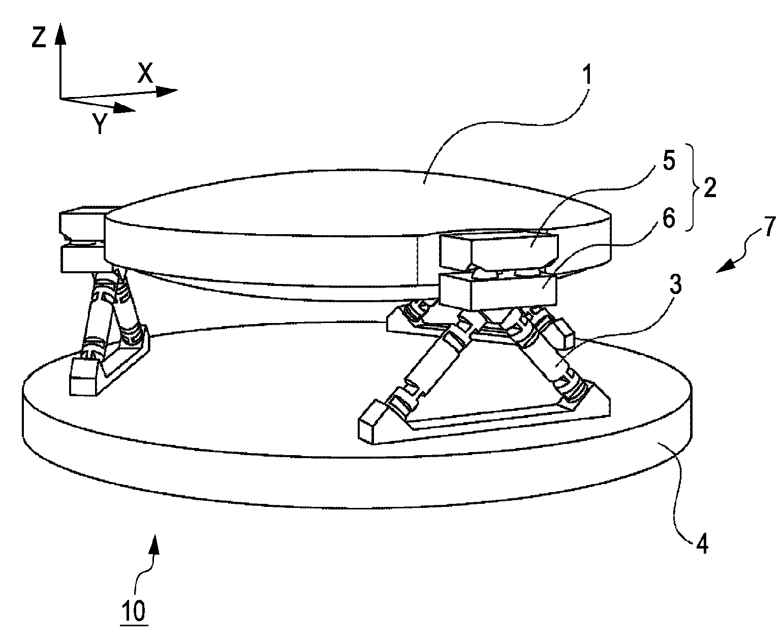
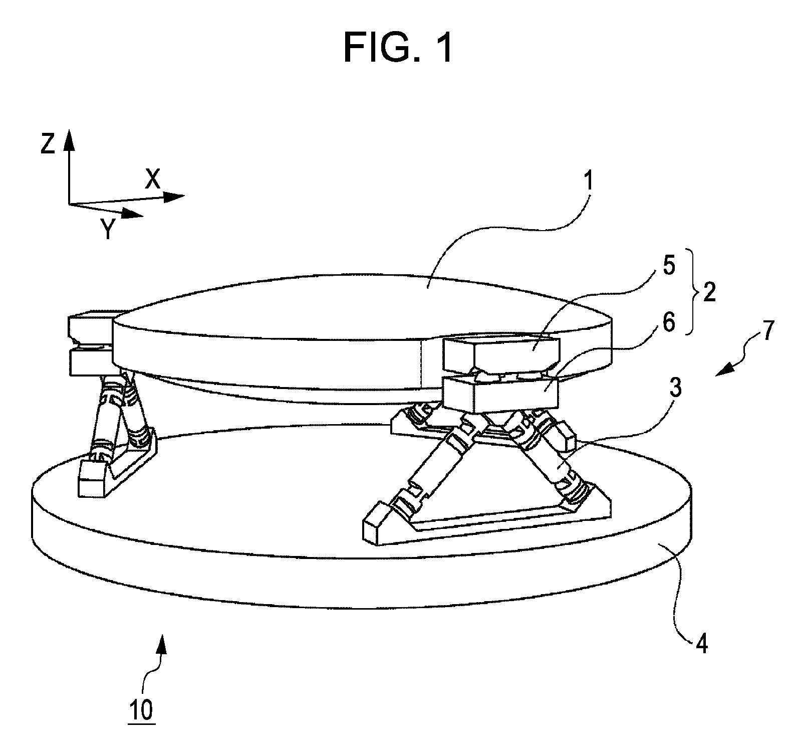
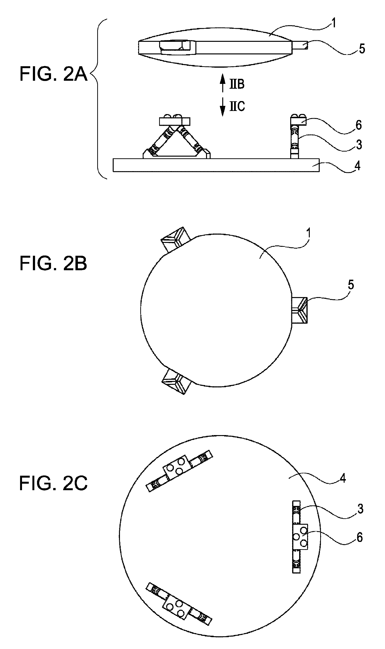
[0037]FIGS. 1 and 2A to 2C illustrate a holding apparatus according to a first embodiment of the present invention. In the figures, a light-axis direction is defined as the Z axis and two perpendicular directions in a plane perpendicular to the Z direction are defined as the X and Y directions. FIG. 1 is a perspective view of the holding apparatus. FIG. 2A is a side view of the holding apparatus in the state in which an object to be held is removed from a base. FIG. 2B illustrates the structure viewed in the direction denoted by IIB in FIG. 2A and FIG. 2C illustrates the structure viewed in the direction denoted by IIC in FIG. 2A.
[0038]In the present embodiment, an optical element 1 is described as an example of an object to be held. In the present embodiment, the optical element is a mirror. However, the optical element can also be, for example, a lens, a parallel plate glass, a prism, a Fresnel zone plate, a kinoform, a binary optics element, or a hologram. The present invention c...
first modification
[0062]A first modification of the first embodiment will now be described. FIGS. 7A to 7C show an example in which a holding member 16 is supported above the base 4 by a flexure member 13, and another holding member 15 is connected to the optical element 1 by another flexure member 17. Although the flexure member 13 is formed integrally with the holding member 16 in FIGS. 7A to 7C, they can also be formed separately from each other. FIG. 7A shows the state before the optical element 1 is removed, FIG. 7B shows the state after the optical element 1 is removed, and FIG. 7C shows the state after the optical element 1 is reattached. Similar to the first embodiment shown in FIGS. 4A to 4C, in FIG. 7C, the optical element 1 is held at substantially the same position as the position shown in FIG. 7A. The manner in which the flexure members 13 and 17 are bent does not largely vary when the optical element 1 is removed and reattached, and therefore the repeatability of the surface shape of th...
second modification
[0063]A second modification of the first embodiment will be described with reference to FIG. 8. In the second modification, each flexure member 3 includes an elastic hinge that is provided with an actuator 9. The actuator 9 is used for elastically deforming the flexure member 3 and for changing the position (including orientation) of the optical element 1. The actuator 9 can be a piezoelectric actuator. Alternatively, the actuator 9 can also be a controllable actuator, such as an inchworm actuator, an electromagnetic actuator, or a hydraulic actuator.
[0064]In addition to changing the position of the optical element 1, the actuator 9 can also be used for intentionally deforming the optical element 1 as necessary.
PUM
 Abstract
Description
Claims
Application Information
 - R&D
- Intellectual Property
- Life Sciences
- Materials
- Tech Scout
- Unparalleled Data Quality
- Higher Quality Content
- 60% Fewer Hallucinations
Browse by: Latest US Patents, China's latest patents, Technical Efficacy Thesaurus, Application Domain, Technology Topic, Popular Technical Reports.
© 2025 PatSnap. All rights reserved.Legal|Privacy policy|Modern Slavery Act Transparency Statement|Sitemap|About US| Contact US: help@patsnap.com


