
Cephalogram image analysis method

a cephalogram and image technology, applied in image analysis, image enhancement, instruments, etc., can solve the problems of time-consuming manual drawing process and achieve the effect of effectively and accurately transforming a cephalogram into a tracing

Inactive Publication Date: 2011-02-01
NAT CHENG KUNG UNIV
View PDF13 Cites 3 Cited by
  • Summary
  • Abstract
  • Description
  • Claims
  • Application Information

AI Technical Summary

Benefits of technology

[0009]One aspect of the present invention is to provide an automated cephalogram image analysis method for effectively and accurately transforming a cephalogram into a tracing without relying on expert experience.
[0016]Hence, with the application of the embodiments of the present invention, a cephalogram can be effectively and accurately converted into a tracing, thus saving time and effort, and avoiding relying on expert experience.

Problems solved by technology

However, such manual drawing process is quite time and effort consuming, and since the definitions of landmarks mostly belong to semantic description, the expert experience of the plotter (physician) will greatly influence the accuracy of the tracing.

Method used


Image

  • Cephalogram image analysis method
  • Cephalogram image analysis method
  • Cephalogram image analysis method

Examples


Embodiment Construction

[0030]Reference will now be made in detail to the preferred embodiments of the present invention, examples of which are illustrated in the accompanying drawings. Wherever possible, the same reference numbers are used in the drawings and the description to refer to the same or like parts.

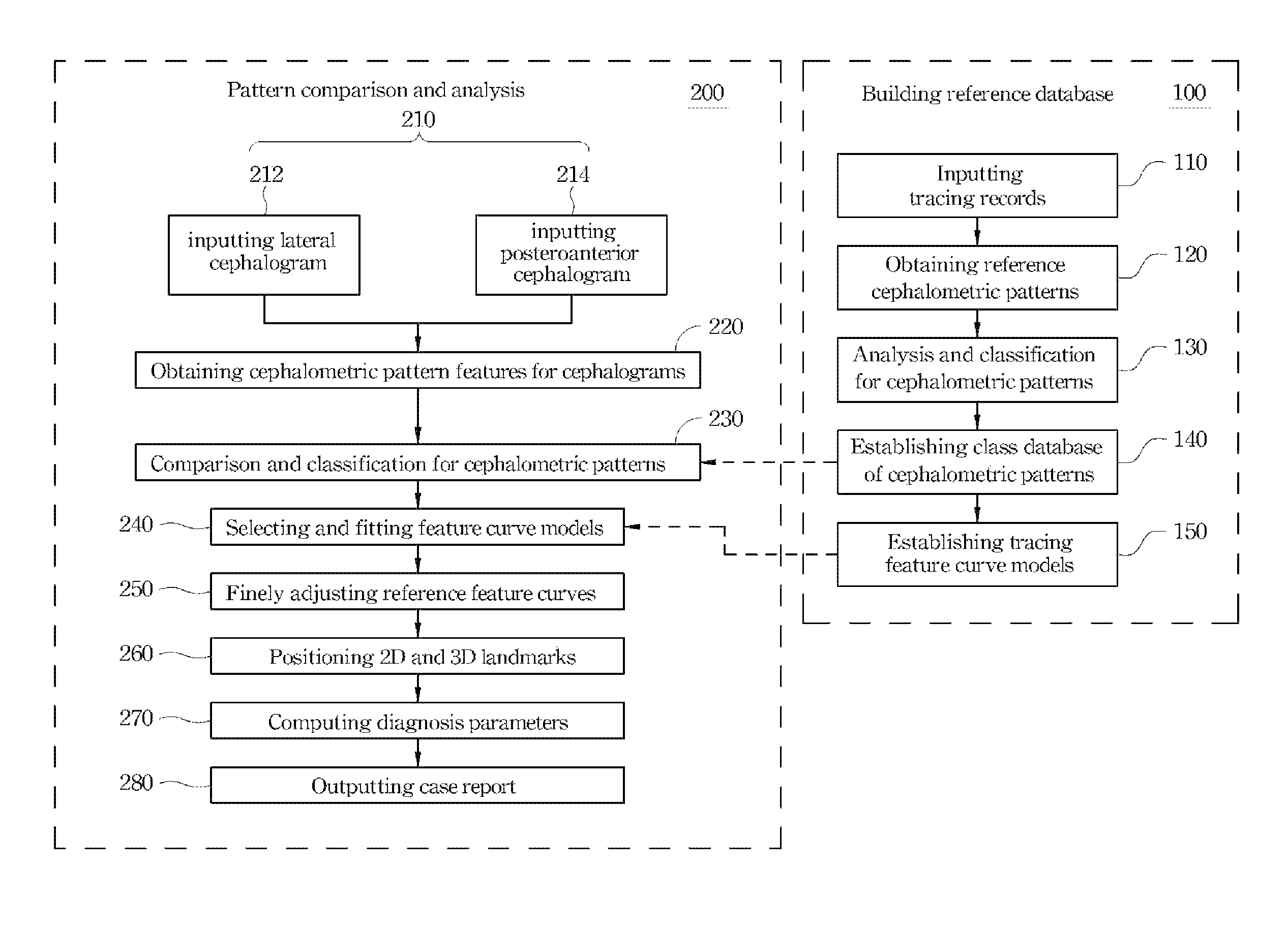
[0031]Referring to FIG. 2, FIG. 2 is a schematic flow chart showing a cephalogram image analysis method according to an embodiment of the present invention. The cephalogram image analysis method of this embodiment comprises a step 100 of building a reference database, and a step 200 of pattern comparison and analysis. In this embodiment, the step 100 of building a reference database is first performed for establishing a set of tracing feature curve models respectively representing a set of reference cephalometric patterns in accordance with a set of tracing records. The so-called “tracing records” mean a set of tracings which have been accumulated and depicted in the past with respect to the historic...


PUM


Abstract

An automated cephalogram image analysis method is disclosed. In this method, a step is first performed for building a reference database in which a set of tracing feature curve models respectively representing a set of reference cephalometric patterns are established based on a set of tracing records. Then, a step of pattern comparison and analysis is performed. In this step, at least one cephalogram is first input, and then a step is performed for comparing the image of the cephalogram with the tracing feature curve models, thereby selecting at least one cephalometric pattern and at least one feature curve model belonging to the cephalometric pattern from the reference cephalometric patterns and the tracing feature curve models. Thereafter, the feature curve model is fitted to the image of the cephalogram so as to obtain at least one tracing of the at least one cephalogram.

Description

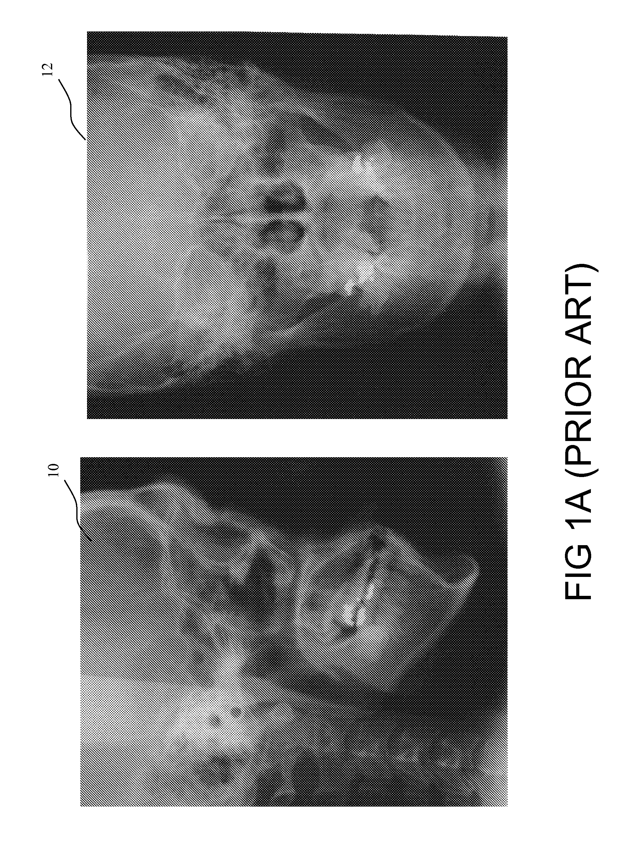
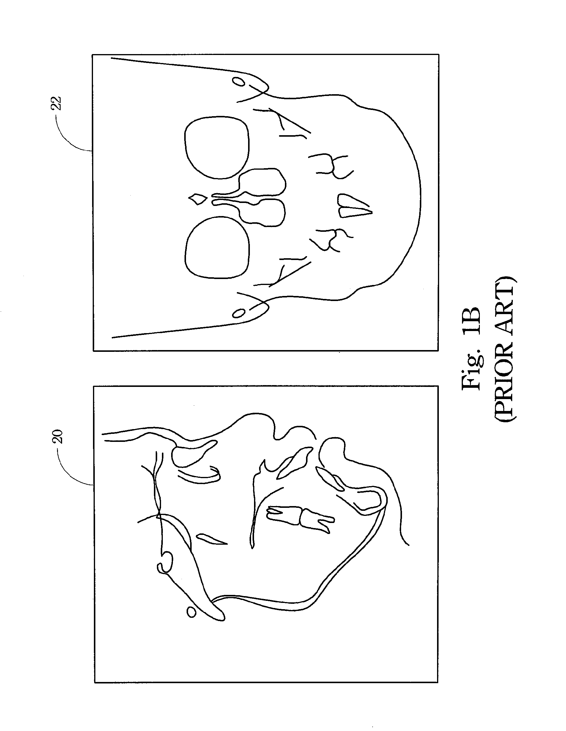
RELATED APPLICATIONS[0001]This application claims priority to Taiwan Application Serial Number 96123375, filed Jun. 27, 2007, which is herein incorporated by reference.BACKGROUND[0002]1. Field of Invention[0003]The present invention relates to a cephalogram image analysis method. More particularly, the present invention relates to a cephalogram image analysis method used for transforming cephalograms into tracings.[0004]2. Description of Related Art[0005]In orthodontic treatment, cephalometry is quite an important metrology technique for analyzing patient's anatomical structure and evaluating the treatment effects. Cephalograms are X-ray films taken at a head portion, and the X-ray films (cephalograms) of posteroanterior view and lateral view are frequently used in clinic.[0006]Referring to FIG. 1A to FIG. 1C, FIG. 1A illustrates a lateral cephalogram 10 and a posteroanterior cephalogram 12; FIG. 1B illustrates a tracing 20 of the lateral cephalogram 10, and a tracing 22 of the post...

Claims


Application Information

Patent Timeline
Patent Type & Authority Patents(United States)
IPC IPC(8): G06K9/00G06V10/44
CPCG06K9/4604G06T7/0014G06T7/0067G06T7/0083G06T7/60G06K2209/05G06K2209/055G06T2207/30008G06T2207/30016G06T7/564G06T7/12G06V10/44G06V2201/03G06V2201/033
Inventor CHENG, KUO-SHENGCHEN, YEN-TINLIU, JIA-KUANG
Owner NAT CHENG KUNG UNIV
Learn More