Method of molding a multi-pole magnetized beverage container holder

a beverage container and magnetized technology, applied in the field of beverage container holders, can solve the problems of difficult or even impossible to retain a beverage without spilling, finding a place to store the beverage container, and simply placing the beverage container on a flat surface is often unsatisfactory, so as to reduce the magnetic force of attraction

Inactive Publication Date: 2011-03-01
ELWARD LOUIS JOINT VENTURE
View PDF54 Cites 38 Cited by
  • Summary
  • Abstract
  • Description
  • Claims
  • Application Information

AI Technical Summary

Benefits of technology

[0014]In yet another embodiment, a magnet assembly includes first and / or second polarized materials and a paramagnetic, superparamagnetic, metamagnetic, ferromagnetic, antiferromagnetic, and / or ferrimagnetic backing plate. The backing plate preferably contacts the magnetic material and is adjacent to, or faces, the interior of the holder to decrease the magnetic force of attraction to the beverage container.

Problems solved by technology

In many of these situations, finding a place to store the beverage container in which the container will not be inadvertently spilled or knocked over can be problematic.
On a boat, for example, simply placing a beverage container on a flat surface is often unsatisfactory since the container may tip over as a result from typical movement of the boat rocking on the water.
Likewise, when operating heavy machinery during construction or farming operations one might find it difficult or even impossible to retain a beverage without spilling.
Similarly, at picnics or other outdoor gatherings, placing a beverage container on the ground may result in spilling as a result of a person or animal inadvertently kicking the container.
While such a holder provides a place for container storage, it also has disadvantages.
For example, the holder is permanently secured in one place on the platform, thus providing limited flexibility for storing such beverage containers.
While additional holders may be installed in areas which are most convenient for such storage, the additional holders may cause clutter in those areas.
Furthermore, if a person wishes to be in an area which does not have a holder installed, that person must either hold the container, or store the container in area which does have a holder, which may be inconvenient for the person due to having to move to the other area every time they wish to drink from the container.

Method used


Image

  • Method of molding a multi-pole magnetized beverage container holder
  • Method of molding a multi-pole magnetized beverage container holder
  • Method of molding a multi-pole magnetized beverage container holder

Examples


Embodiment Construction

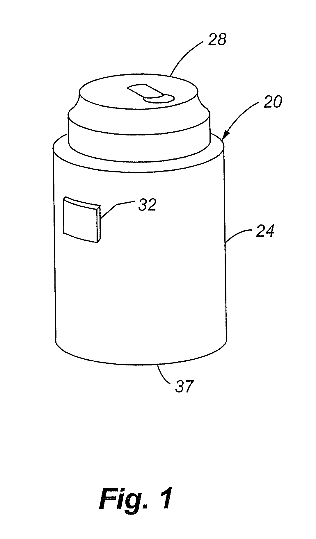
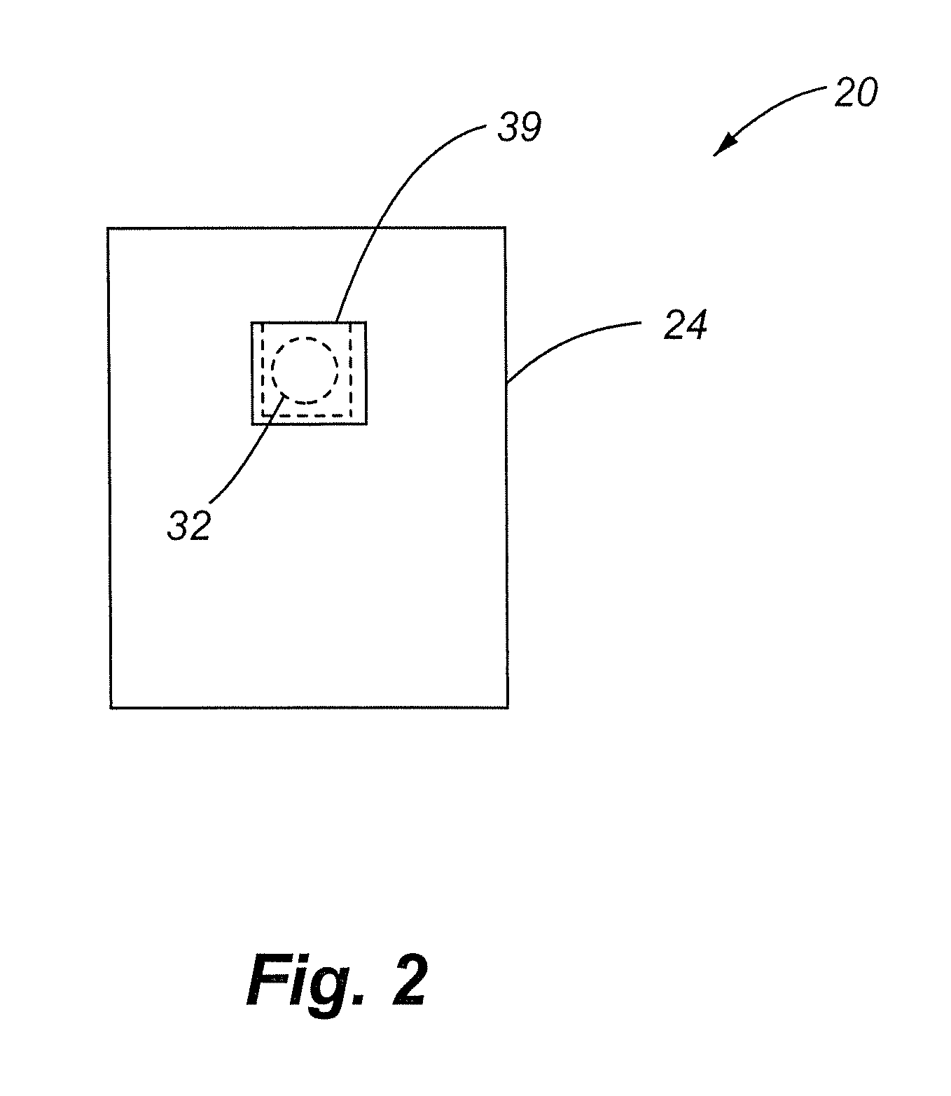
[0048]Referring to FIG. 1, an illustration of a beverage container holder 20 of one embodiment of the present invention is described. The beverage container holder 20 includes a sleeve 24 into which a beverage container 28 may be placed. The beverage container holder 20 also includes a magnet 32 which is secured to the sleeve 24. The beverage container holder 20 may also include a base 37 which helps to prevent the beverage container 28 from sliding completely through the sleeve 24 and can provide additional insulation. The magnet 32 serves to mount container holder 20 to any mounting surface. As used herein, mounting surface refers to any surface to which the beverage container holder 20 may be mounted. Mounting surfaces include paramagnetic, superparamagnetic, metamagnetic, ferromagnetic, ferrimagnetic and antiferromagnetic materials (e.g., ferrous materials), and diamagnetic or superdiamagnetic materials (e.g., non-ferrous materials), which have a paramagnetic, superparamagnetic,...


PUM

PropertyMeasurementUnit
magnetic forceaaaaaaaaaa
heightaaaaaaaaaa
diameteraaaaaaaaaa

Abstract

A beverage container holder is disclosed which includes a magnet within the sleeve of a beverage container holder. The beverage container holder, along with any beverage container placed in the beverage container holder, may be mounted on any mounting surface having an associated ferrous material. The beverage container holder is held in place due to the force of the magnetic interaction between the magnet and the mounting surface.

Description

CROSS REFERENCE TO RELATED APPLICATION[0001]The present application is a continuation-in-part under 35 U.S.C. §120 of U.S. patent application Ser. No. 10 / 382,459, filed Mar. 5, 2003, entitled “Magnetized Beverage Container Holder”, and claims priority under 35 U.S.C. §119(e) from U.S. Provisional Application Ser. No. 60 / 866,326, filed Nov. 17, 2006, of the same title, which is incorporated herein by this reference.FIELD OF THE INVENTION[0002]The present invention relates generally to holders for beverage containers, and more specifically, to a magnetized beverage container holder used to secure a beverage container to a surface.BACKGROUND OF THE INVENTION[0003]In numerous situations, for several reasons, people drink beverages from beverage containers, such as boating, tailgating, working, etc. For example, while boating a person may be exposed to heat and sun for several hours, and remaining hydrated is important. In many of these situations, finding a place to store the beverage c...

Claims


Application Information

Patent Timeline
Patent Type & Authority Patents(United States)
IPC IPC(8): B29C45/14A63B37/00A47K1/08A47G1/17A47G23/02
CPCA47G23/0225A47G2200/106
Inventor MITCHELL, JED
Owner ELWARD LOUIS JOINT VENTURE
Why Eureka
Try Eureka