

Air handling chamber
a technology for air handling and chambers, which is applied in the direction of parkings, buildings, walls, etc., can solve the problems of difficult interstitial material sealing at the joints, high temperature in the outside or roof chambers, and high humidity, so as to improve sealing, prolong leakage path, and stabilize the structure
- Summary
- Abstract
- Description
- Claims
- Application Information
AI Technical Summary
Benefits of technology
Problems solved by technology
Method used
Image

Examples
Embodiment Construction
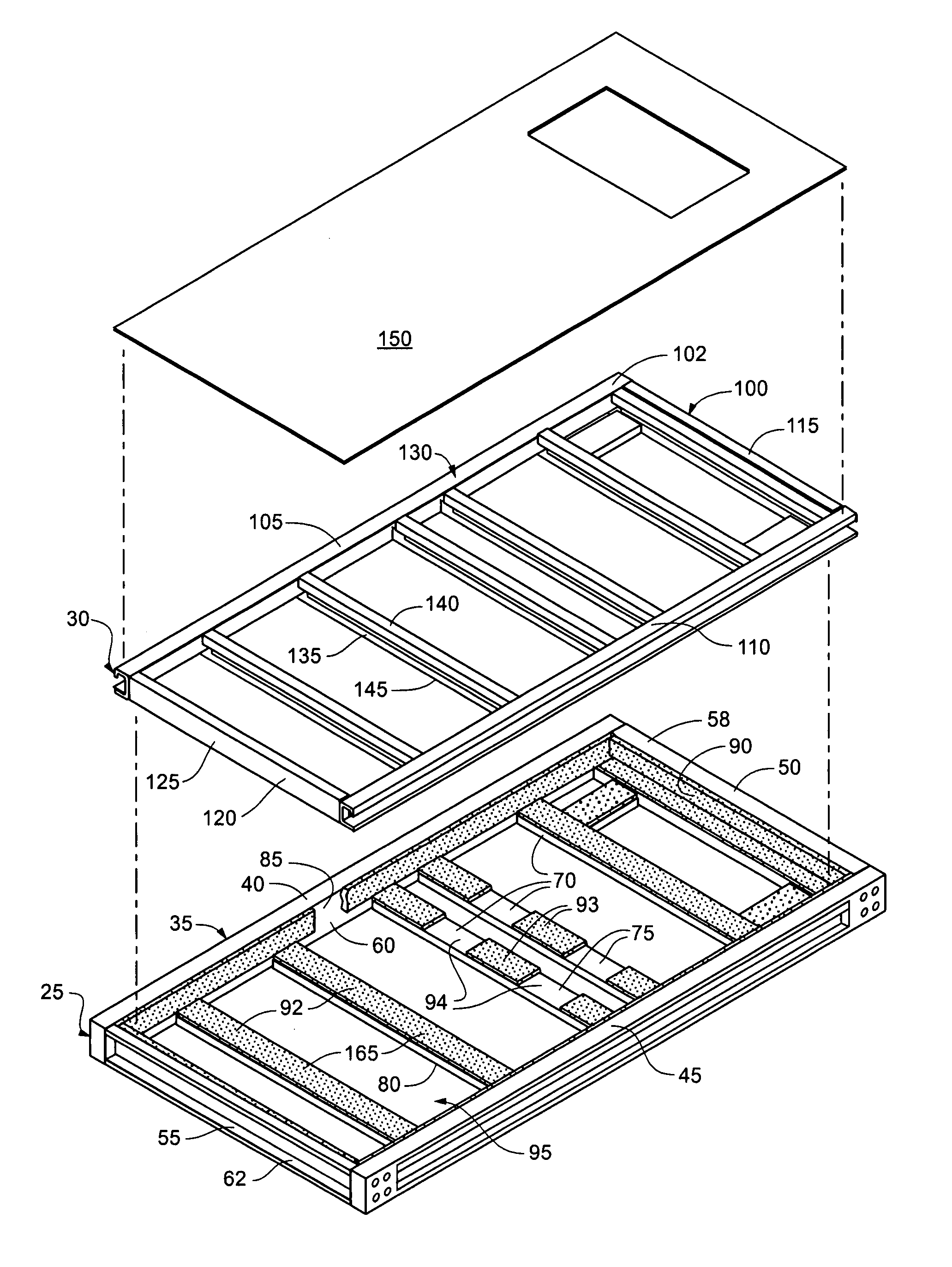
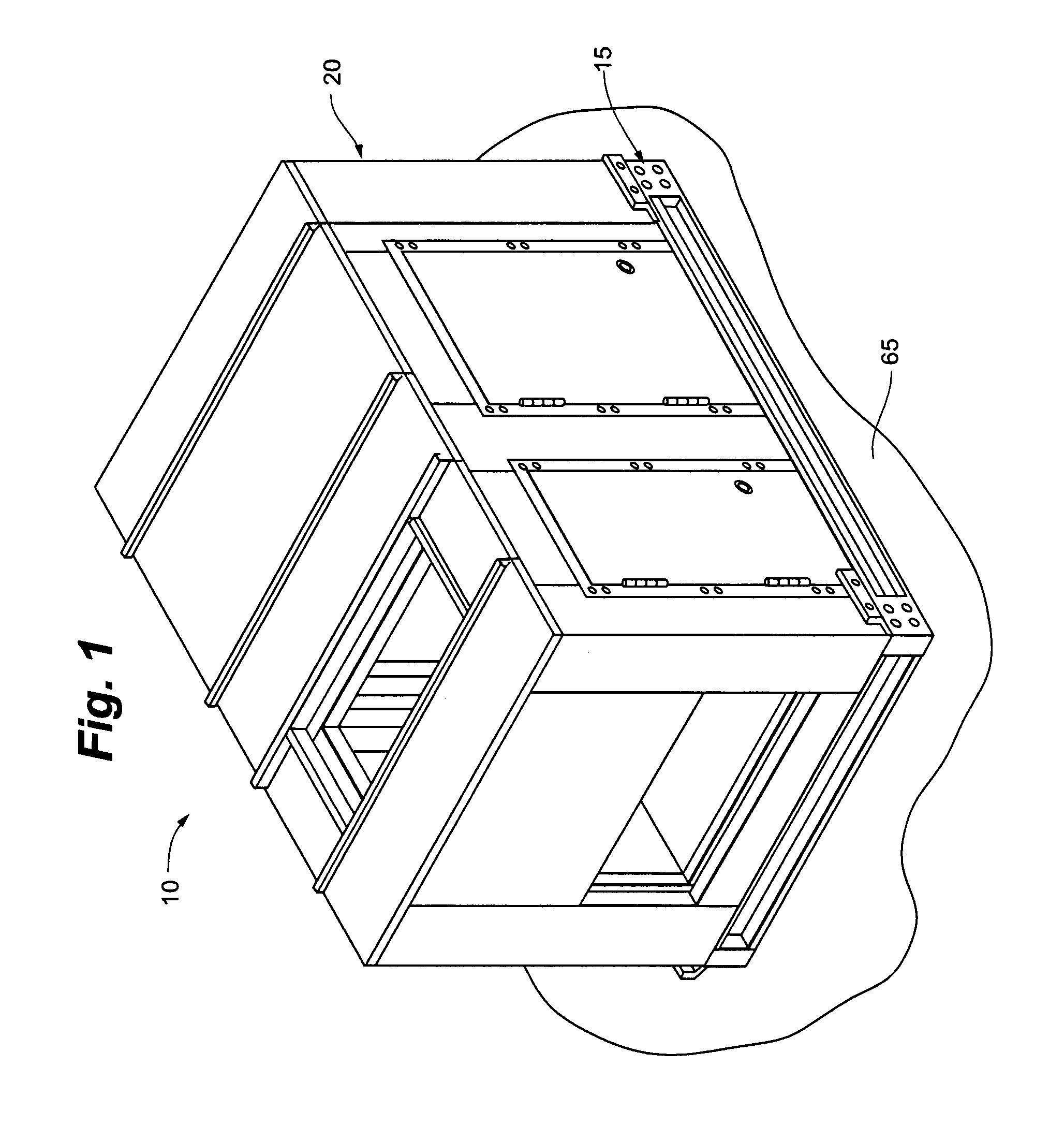
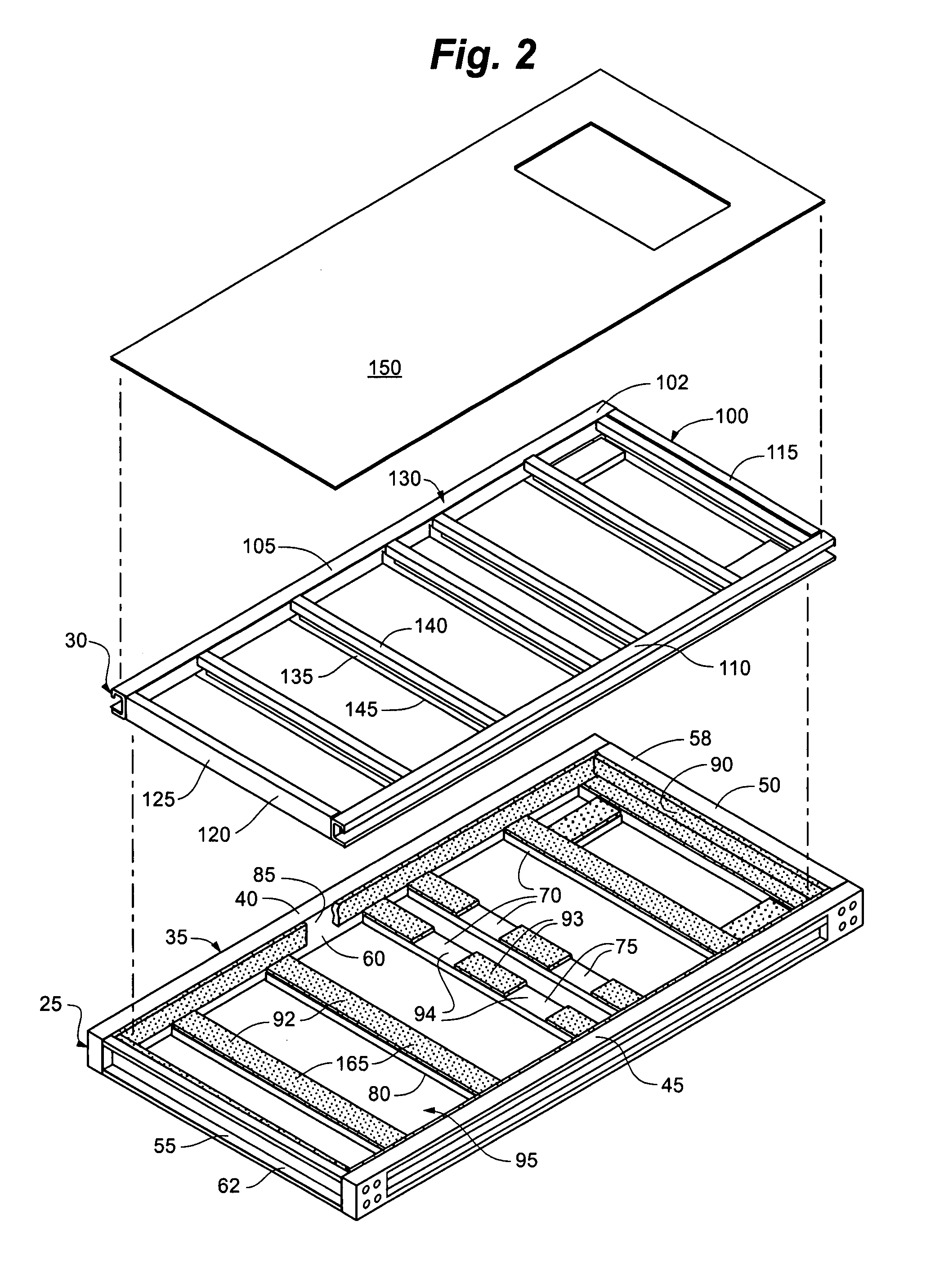
Referring to the drawings, a thermally broken chamber 10 includes a base assembly 15 and an upper assembly 20. Referring to FIGS. 2 through 4, the base assembly 15 includes an exterior base 25 and an interior base 30. The exterior base 25 is generally rectangular and has an exterior frame 35 having side members 40, 45 and end members 50, 55. The exterior frame 35 defines an interior perimeter 60, and outer perimeter 62 and a lower or grounding plane 65. The exterior base 25 also includes a number of cross members 70 that extend between the side members 40 and 45 of the base frame 35. The cross members 70 each have an upper surface 75 and a lower surface 80. The lower surfaces 80 of the cross members 70 may be arranged flush with the lower plane 65, as illustrated in FIGS. 2 and 6.
The interior perimeter 60 of the exterior frame 35 has an upper portion 85 extending above the upper surfaces 75 of the cross members 70, best portrayed in FIG. 4. The upper portion 85 of the interior perim...
PUM
 Abstract
Description
Claims
Application Information