Screen

a screen and screen body technology, applied in the field of screens, can solve the problems of increasing weight, complicated screen body configuration, and not being suitable for portable-type screens used by users

Inactive Publication Date: 2011-05-31
SEIKO EPSON CORP
View PDF8 Cites 11 Cited by
  • Summary
  • Abstract
  • Description
  • Claims
  • Application Information

AI Technical Summary

Benefits of technology

[0016]The screen has a two-section structure having the first pantograph mechanism and the second pantograph mechanism, which are installed respectively between the first supporting unit and the second supporting unit about the fixed column which is substantially at the center. In this configuration, in comparison with the screen provided with the pantograph mechanism having the first pantograph mechanism and the second pantograph mechanism formed integrally with each other and held by the fixed column, the flexibility of the position of arrangement of the first pantograph mechanism and the second pantograph mechanism with respect to the screen body and the fixed column is increased. Therefore, the center of the weight balance of the screen may be set in the direction of the column of the fixed column, so that it is not necessary to compensate the weight balance by increasing the thickness of the fixed column as in the related art.
[0039]According to the screen as described above, since the fixed column and the plurality of arm members which constitute the first pantograph mechanism and the second pantograph mechanism are formed of the hollow column-shaped member, a force of rigidity required for the fixed column and the plurality of arm members could be secured. Furthermore, the possibility that the user's finger could be caught between the intersecting arm members when expanding and contracting (specifically when folding) the first pantograph mechanism and the second pantograph mechanism is reduced.

Problems solved by technology

However, the screen disclosed in JP-A-2007-219279 has problems such that the configuration of the screen body is generally complicated and is upsized, thereby increasing the weight.
Therefore, it is not suitable as a portable-type screen used by being carried by users.
Accordingly, the portability of the screen is lowered, which results in lowering of the convenience of the screen.
However, the dummy weight simply results in weight increase, so that there arises a problem of lowering of the portability.

Method used


Image

  • Screen
  • Screen
  • Screen

Examples


first embodiment

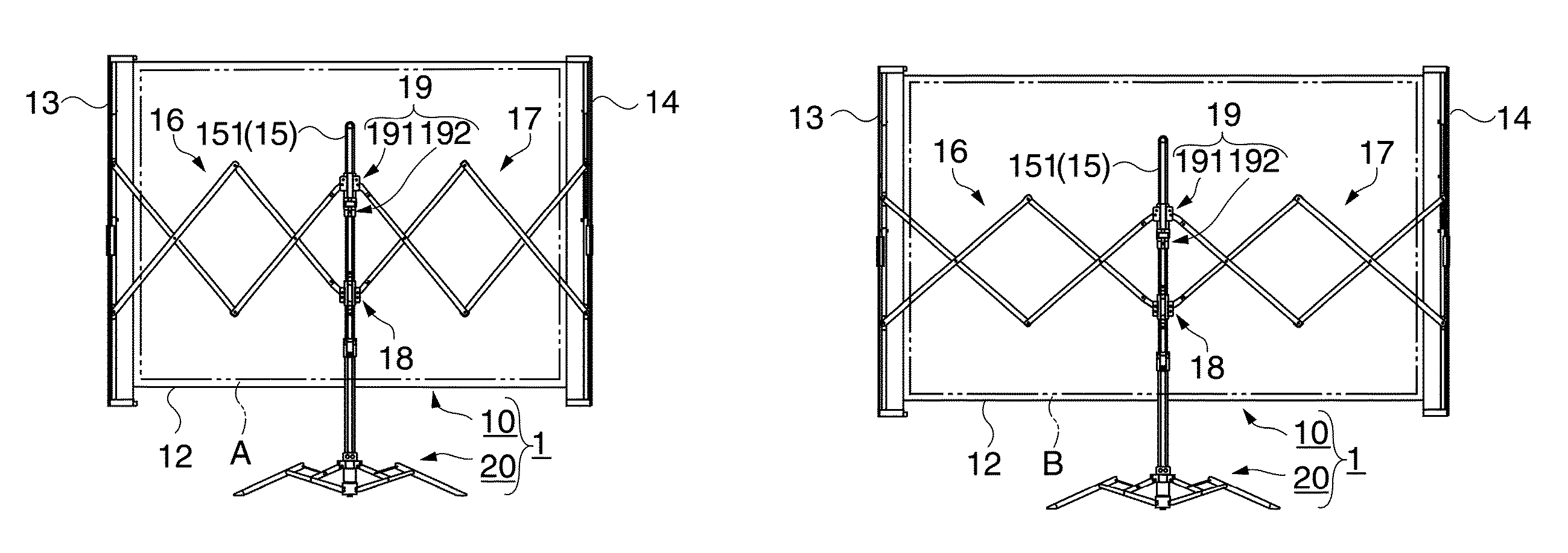
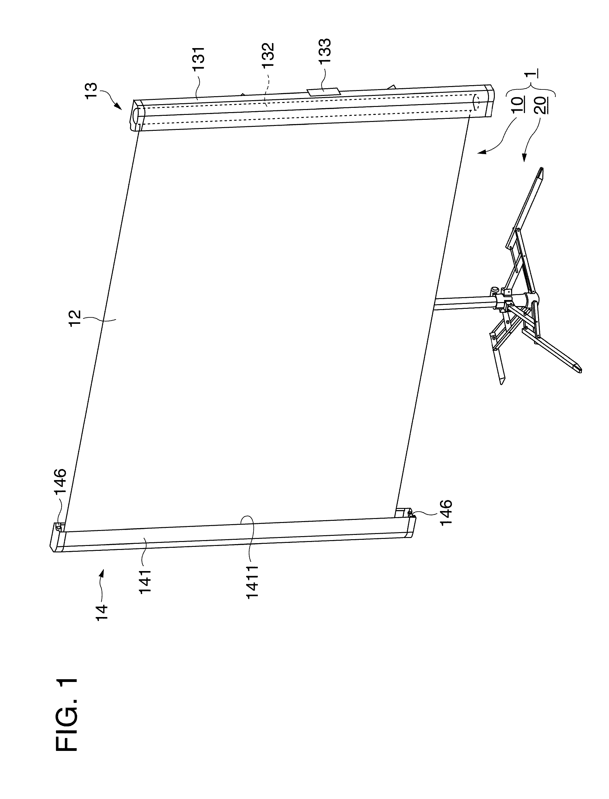
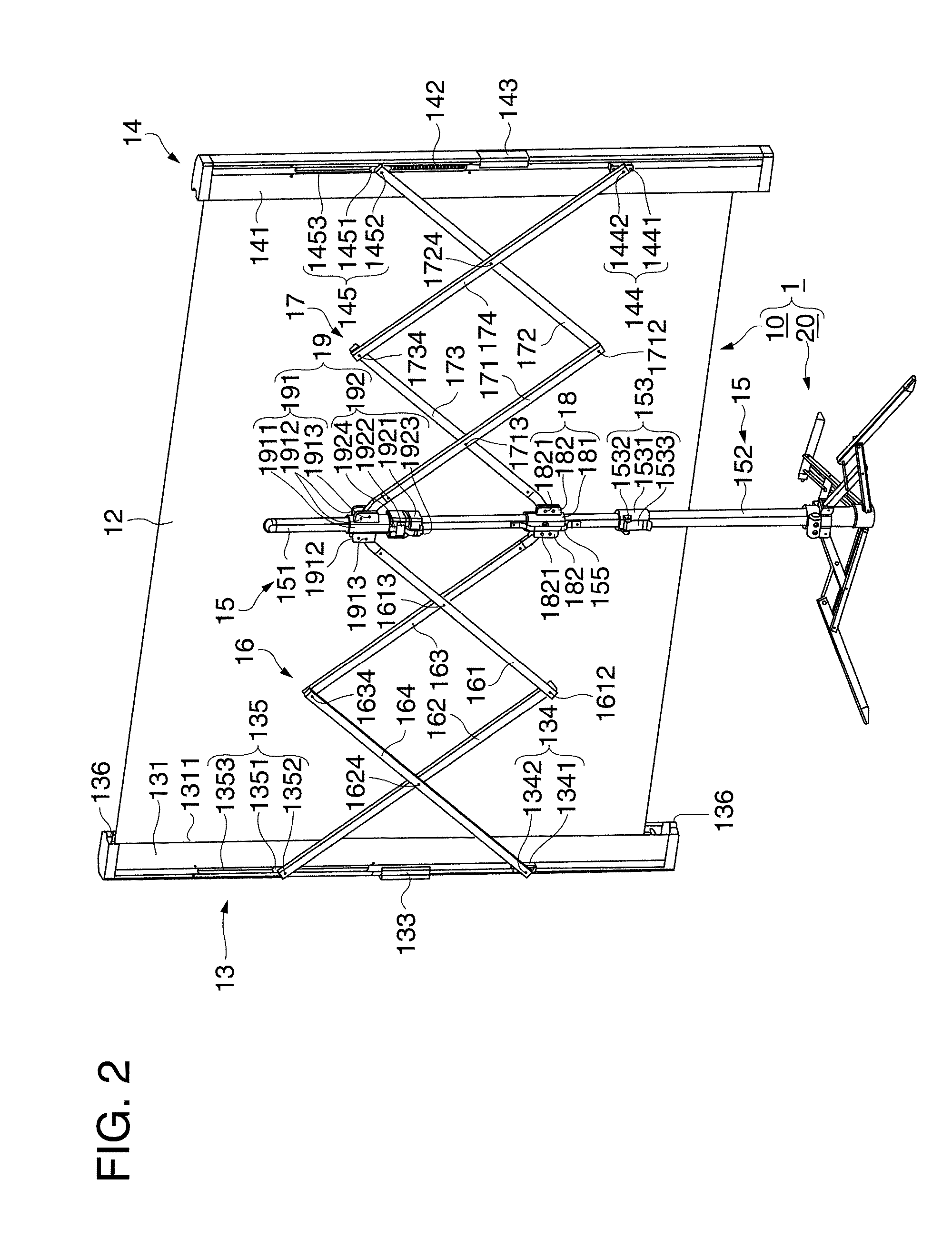
[0062]FIG. 1 and FIG. 2 are perspective views showing a schematic configuration of a screen according to a first embodiment. FIG. 1 is a perspective view of a screen 1 viewed from the front from which image light enters, and FIG. 2 is a perspective view of the screen 1 viewed from the back side. FIG. 3 is a partially enlarged view of a principal portion of the screen viewed from the back side. FIG. 3 shows a second pantograph mechanism 17, a fixed column 15, a second supporting unit 14, and so on. Referring now to FIGS. 1 to 3, the configuration of the screen 1 will be described. The “left” and “right” described below mean the left and right of the screen 1 when viewed from the back side.

[0063]On the screen 1, the image light projected in an enlarged scale, for example, from a projector or the like, not shown, is projected. As shown in FIG. 1 and FIG. 2, the screen 1 roughly includes an image projecting portion 10 and a supporting leg 20.

[0064]As shown in FIG. 1 or FIG. 2, the image...

second embodiment

[0179]FIG. 13 is a partial enlarged drawing when viewing a principal portion of a screen according to a second embodiment from the back side. A screen 2 in the second embodiment is different from the screen 1 in the first embodiment only in the position to install a coil spring 148 as the urging member (which corresponds to the coil spring 142 in the first embodiment), and other members are the same as the first embodiment. In FIG. 13, the same components as in the first embodiment are designated by the same reference numerals. Therefore, in the following description, only the configurations different from the first embodiment will be described.

[0180]In the screen 2 in the second embodiment, the coil spring 148 as the urging member is hooked on the pivotal shaft 1712 and the pivotal shaft 1734 which constitute the second pantograph mechanism 17 as shown in FIG. 13. The coil spring 148 is formed as a tension coil spring, and includes a spring body 1481 and hooks 1482 formed at both e...

third embodiment

[0183]FIG. 14 is a partial enlarged drawing viewing a principal portion of a screen according to a third embodiment from the back side. A screen 3 in the third embodiment is different from the screen 1 in the first embodiment only in the position to install a coil spring 200 as the urging member (which corresponds to the coil spring 142 in the first embodiment), and other members are the same as the first embodiment. In FIG. 14, the same components as in the first embodiment are designated by the same reference numerals. Therefore, in the following description, only the configurations different from the first embodiment will be described. In FIG. 14, the fixed column 15, the arm sliding unit 19, and the arm fixing unit 18 are shown and other members such as the first pantograph mechanism 16 and the second pantograph mechanism 17 are not shown.

[0184]According to the screen 3 in the third embodiment, the coil spring 200 as the urging member is installed in the interior of the first fi...


PUM


Abstract

A screen includes: a flexible screen body on which image light is projected; a fixed column arranged in a central portion; an arm sliding unit configured to pivotably support the second arm member of the first pantograph mechanism and the second arm member of the second pantograph mechanism with respect to the fixed column so as to be slidable in the vertical direction, in which the first pantograph mechanism and the second pantograph mechanism are expanded and contracted to move the first supporting unit and the second supporting unit toward and away from each other by a sliding movement of the arm sliding unit, and an urging member configured to urge the first supporting unit and the second supporting unit to move away from each other is provided.

Description

[0001]The entire disclosure of Japanese Patent Application No. 2008-178724, filed Jul. 9, 2008, is expressly incorporated by reference herein.BACKGROUND[0002]1. Technical Field[0003]The present invention relates to a screen.[0004]2. Related Art[0005]Screens in the related art are used by projecting image light projected from a projector or the like in an enlarged scale on a screen surface of a flexible sheet type screen body. Among these screens, there are various portable-type screens used by being carried by users.[0006]Among the portable-type screens, a screen used by opening and closing the screen body in the lateral direction generally includes a screen body on which image light is projected, columns for supporting the screen body on the right side and the left side, opening and closing mechanism for opening and closing the screen body in the lateral direction, and a main column for holding the screen body, the columns, and the opening and closing mechanism. These components ar...

Claims


Application Information

Patent Timeline
Patent Type & Authority Patents(United States)
IPC IPC(8): G03B21/56
CPCG03B21/56
Inventor YUZAWA, FUMIO
Owner SEIKO EPSON CORP
Why Eureka
Try Eureka