Voltage regulator

a voltage regulator and voltage technology, applied in the direction of electric variable regulation, process and machine control, instruments, etc., can solve the problems of operation instability, difficult design of voltage regulators with small power consumption, etc., and achieve the effect of improving the transient response performance stability and improving the transient response characteristics

Inactive Publication Date: 2011-09-27
ABLIC INC
View PDF3 Cites 4 Cited by
  • Summary
  • Abstract
  • Description
  • Claims
  • Application Information

AI Technical Summary

Benefits of technology

[0016]Hence, a voltage regulator according to the present invention is configured to detect a state in which an absolute value of a difference between a reference voltage and a referred voltage becomes larger than a predetermined value, and make moderate the fluctuations of an operating point due to a feedback system of the output current during a given period of time since the detection, thereby suppressing an unstable operation. Further, the voltage regulator is configured to detect a state in which the reference voltage and the referred voltage are not equal to each other, and stop the fluctuations of output current during a given period of time since that state and then start a feedback operation of the output current after a given period of time.
[0018]The essence of the present invention is to provide a delay to fluctuations of an operating point in the feedback system of the output current with respect to the fluctuations of an operating point of a normal feedback system. Therefore, it is apparent that the same effect can also be obtained with a structure in which the feedback system itself of the output current detects an abrupt increase of the output current to make moderate an increase of current in a differential amplifier circuit.
[0019]According to the voltage regulator of the present invention, there is employed a circuit structure in which a state where an absolute value of a difference between a reference voltage and a referred voltage becomes larger than a predetermined value and the fluctuations of an operating point due to a feedback system of the output current is made moderate during a given period of time since that state. Therefore, it is possible to provide a voltage regulator capable of improving the transient response characteristics under heavy load while suppressing the power consumption under light load, in which performance stability in a transient response is improved.

Problems solved by technology

This indicates the existence of a trade off between the input / output voltage difference and the current consumption, which leads designing of a voltage regulator having small power consumption to difficult.
Therefore, in a case where operating points of both the systems are simultaneously moved, the operation may become unstable due to interaction of the respective feedback systems.

Method used


Image

  • Voltage regulator
  • Voltage regulator
  • Voltage regulator

Examples


first embodiment

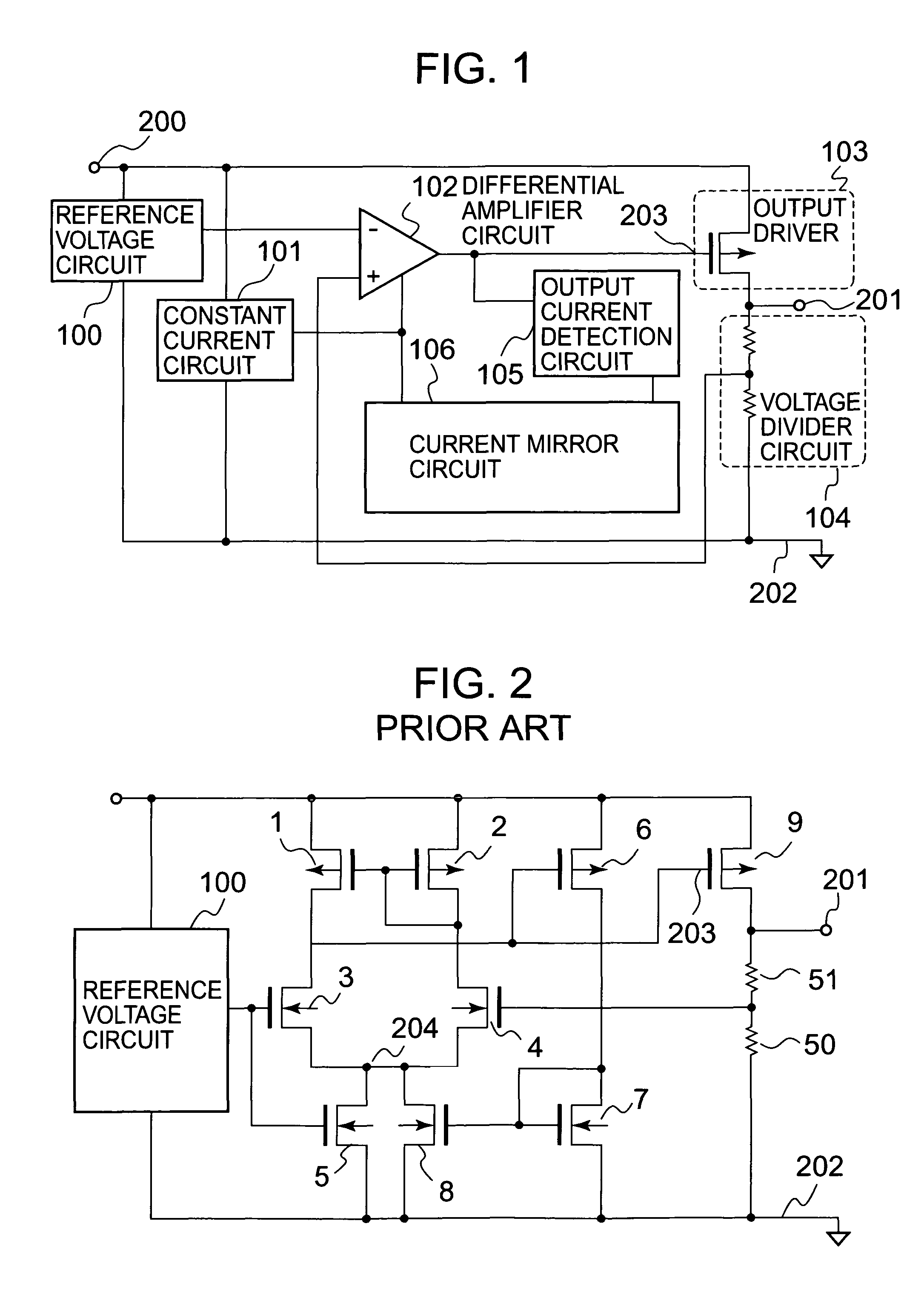
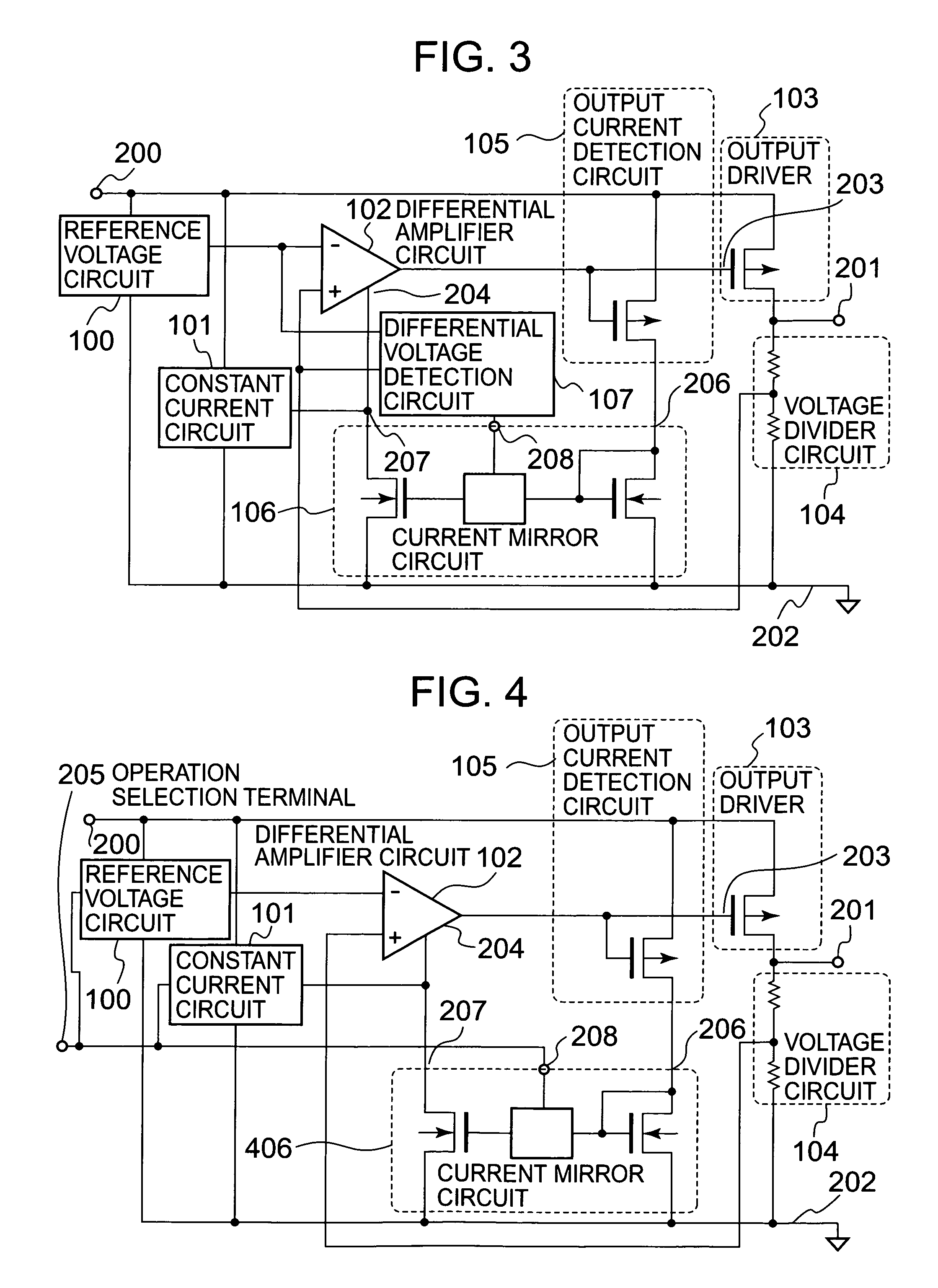
[0035]FIG. 3 is a circuit diagram of a voltage regulator according to a first embodiment of the present invention.

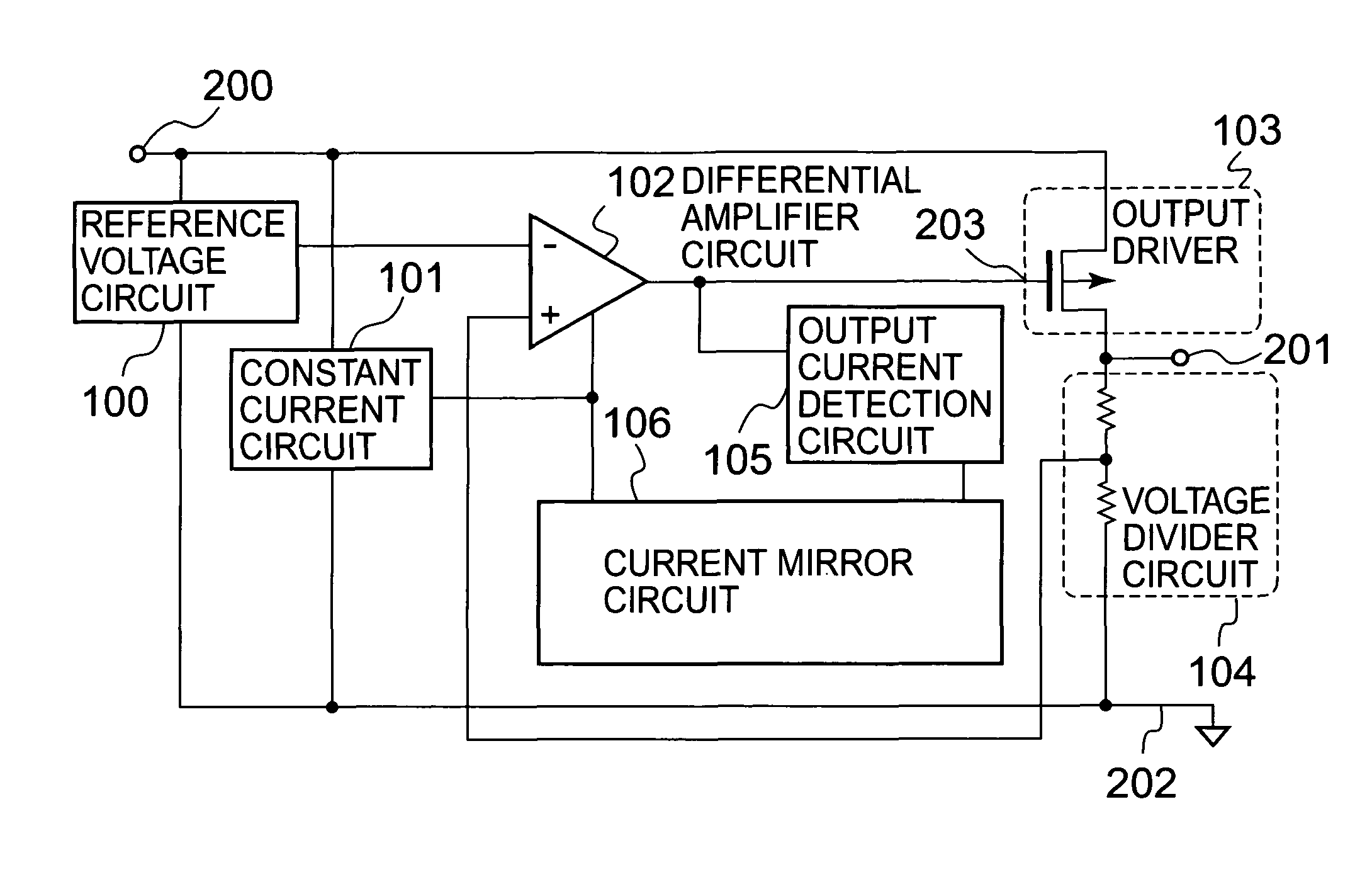
[0036]The voltage regulator according to the first embodiment of the present invention includes a reference voltage circuit 100, a constant current circuit 101, a differential amplifier circuit 102, an output driver 103, a voltage divider circuit 104, an output current detection circuit 105, a current mirror circuit 106, and a differential voltage detection circuit 107.

[0037]The reference voltage circuit 100 is connected between an input terminal 200 input with a power supply voltage and a ground terminal 202, and supplies a constant reference voltage VREF to an inverting input terminal of the differential amplifier circuit 102, irrespective of an input voltage. The output driver 103 is connected to the input terminal 200 and an output terminal 201, and a control terminal 203 of the output driver 103 is controlled based on an output of the differential amplifier circuit ...

second embodiment

[0051]FIG. 4 is a circuit diagram of a voltage regulator according to a second embodiment of the present invention.

[0052]The voltage regulator according to the second embodiment of the present invention includes a reference voltage circuit 100, a constant current circuit 101, a differential amplifier circuit 102, an output driver 103, a voltage divider circuit 104, an output current detection circuit 105, and a current mirror circuit 406. The voltage regulator according to the second embodiment is different from the voltage regulator according to the first embodiment of FIG. 3, in that the current mirror circuit 406 instead of the current mirror circuit 106 and an operation selection terminal 205 instead of the differential voltage detection circuit 107 are provided.

[0053]Operations other than those of the current mirror circuit 406 and the operation selection terminal 205 are the same as those of the voltage regulator according to the first embodiment of FIG. 3, and hence descripti...


PUM


Abstract

A voltage regulator stably operates even when an operating current of a differential amplifier circuit is increased according to an output current. In the voltage regulator, a current mirror circuit for detecting the output current and increasing the operating current of the differential amplifier circuit is provided with a function of providing a delay according to an operation state of the voltage regulator. A simultaneous action of a main feedback system and a feedback system for the output current is eliminated, whereby an internal operating point can be prevented from fluctuating and therefore stability of the operation is improved.

Description

BACKGROUND OF THE INVENTION[0001]1. Field of the Invention[0002]The present invention relates to a voltage regulator for outputting a constant voltage, and more particularly, to a reduction in power consumption of a voltage regulator.[0003]2. Description of the Related Art[0004]A voltage regulator is aimed to supply a stable voltage to an electronic device connected to an output, irrespective of fluctuations of an input voltage or output current supplied to a load. The voltage regulator has a wide range of use, and is used for stably operating information devices, portable communication devices, and the like.[0005]In the portable communication devices, to achieve downsizing and lightening of batteries, thereby prolonging the operation time, is a top priority from the viewpoint of nature of the device. For combined attainment of securing a long operation time and downsizing and lightening of the batteries, reduction of power consumption of the device including the voltage regulator i...

Claims


Application Information

Patent Timeline
Patent Type & Authority Patents(United States)
IPC IPC(8): G05F1/40
CPCG05F1/575G05F3/26G05F3/02G05F3/16
Inventor IMURA, TAKASHI
Owner ABLIC INC
Why Eureka
Try Eureka