Golf ball surface patterns comprising variable width/depth multiple channels

a golf ball and variable-width technology, applied in the field of golf balls, can solve the problems of small dimples not always very effective in reducing drag and increasing lift, space does not improve the aerodynamic performance of the golf ball, and the effect of increasing the flight symmetry

Inactive Publication Date: 2011-10-11
ACUSHNET CO
View PDF47 Cites 29 Cited by
  • Summary
  • Abstract
  • Description
  • Claims
  • Application Information

AI Technical Summary

Benefits of technology

[0012]In some embodiments, these channels may allow the golf ball to have orientation-specific aerodynamic properties, i.e., to fly differently depending on its orientation when hit off of a tee. In other embodiments, the channels allow the ball to have greater flight symmetry. In some embodiments, there may be both channels and dimples or other features on the surface of the golf ball.

Problems solved by technology

This is the primary source of drag for golf balls.
In arranging the dimples, an attempt is made to minimize the space between dimples, because such space does not improve aerodynamic performance of the ball.
However, in reality small dimples are not always very effective in decreasing drag and increasing lift.
This results at least in part from the susceptibility of small dimples to paint flooding.
Paint flooding occurs when the paint coat on the golf ball fills the small dimples, and consequently decreases the dimple's aerodynamic effectiveness.

Method used


Image

  • Golf ball surface patterns comprising variable width/depth multiple channels
  • Golf ball surface patterns comprising variable width/depth multiple channels
  • Golf ball surface patterns comprising variable width/depth multiple channels

Examples


Embodiment Construction

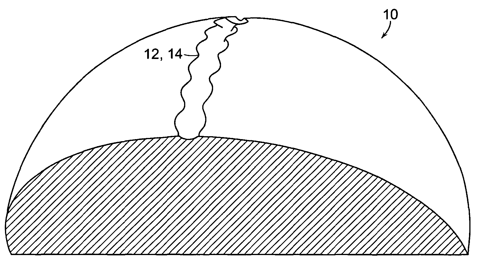
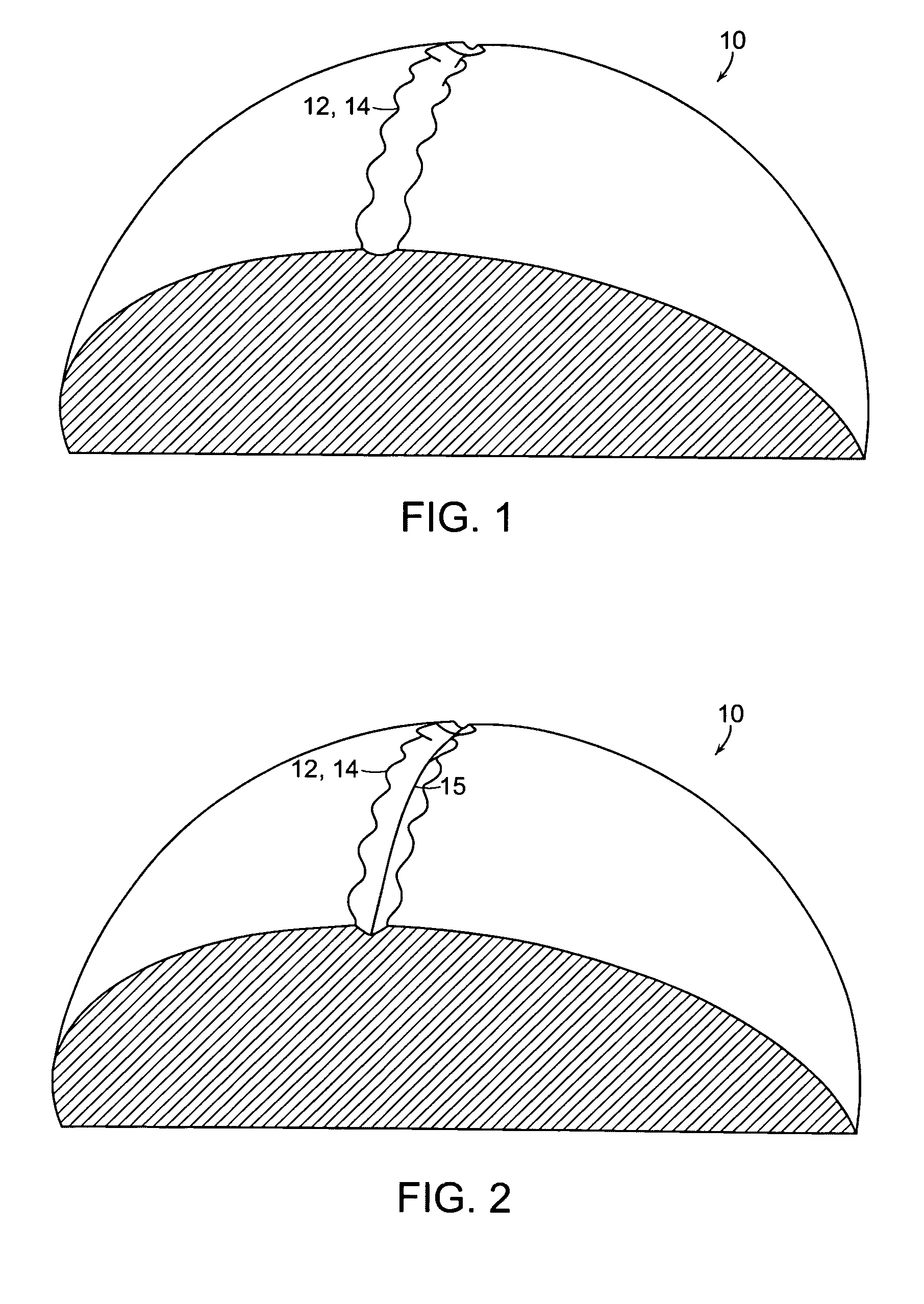
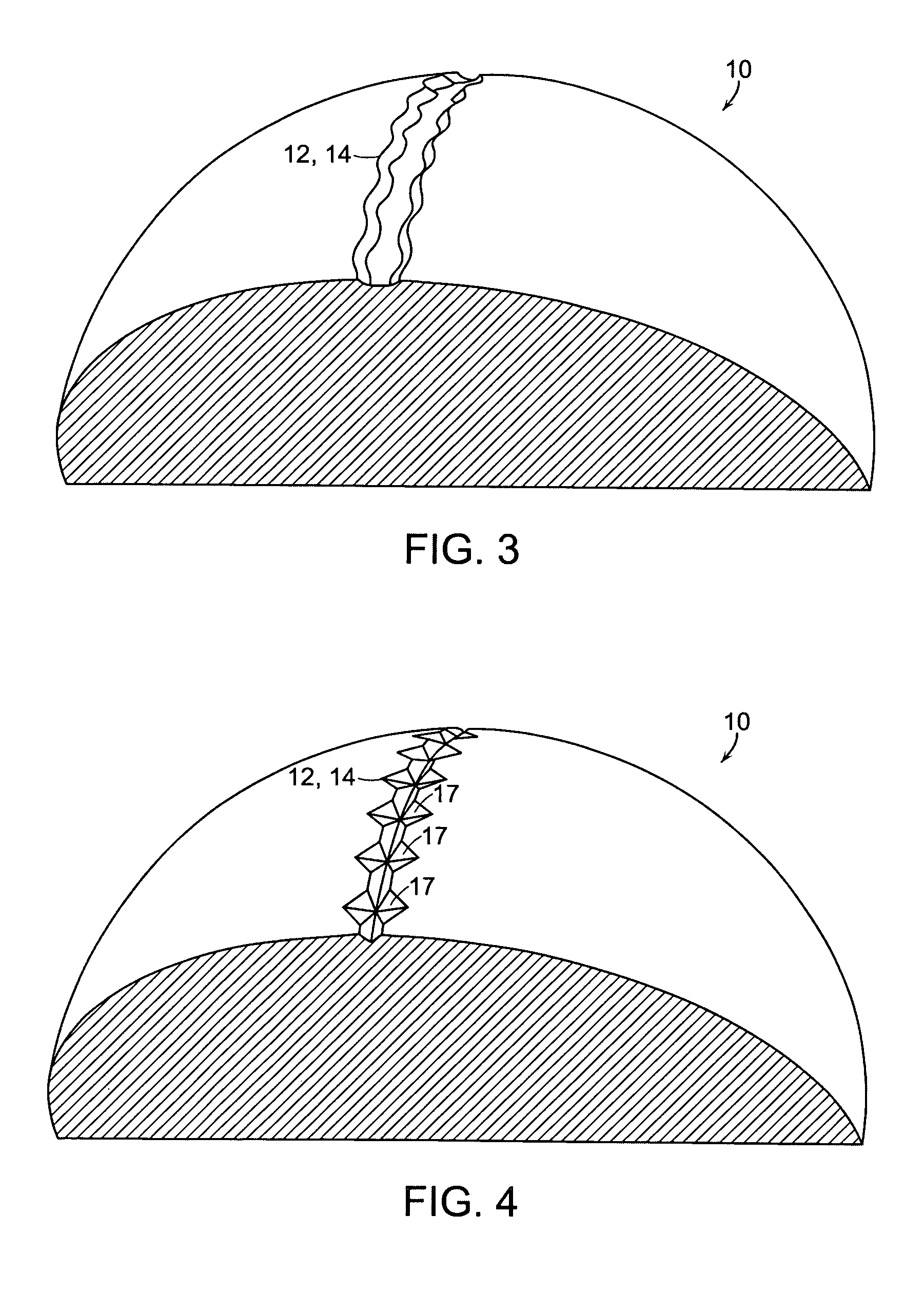
[0021]In one embodiment as illustrated in FIGS. 1-12, the present invention comprises a golf ball 10 having a system of bands, comprising one or more bands 12 to improve the ball's aerodynamics. Bands 12 are disclosed in the parent case, albeit with smooth side edges and without features to enhance the bands' appearance and aerodynamic properties, as described and claimed herein. A band 12 may be a surface channel 14, as in FIGS. 1-11, or a raised bead 16, as in FIG. 12. Channels 14 have an elevation lower than the outer surface of ball 10, and beads 16 have an elevation higher than the outer surface of ball 10. Bands 12 have a variable width and / or depth / height, either within the same band (intra-band) or between bands (inter-band), and may be continuous or discontinuous. Bands 12 may have any desired shape or pattern. This may include, but is not limited to, geometric patterns, fractal patterns, irregular patterns, linear and non-linear lines, and the like. In one embodiment, it m...


PUM


Abstract

A golf ball having an improved surface pattern is disclosed. The golf ball has one or more bands on its surface. These bands may be either channels or raised beads. The bands have variable widths and / or heights / depths, either within the same band or between bands. These bands may decrease drag, or may increase lift. These bands may be linear, or may be curved, and may or may not fully circumscribe the golf ball. These channels or ridges may also be combined with traditional or non-traditional dimples.

Description

CROSS-REFERENCE TO RELATED PATENT APPLICATIONS[0001]This application is a continuation-in-part of U.S. patent application Ser. No. 12 / 233,649, filed on Sep. 19, 2008, which is incorporated by reference herein in its entirety, which is itself a continuation in part of Ser. No. 11 / 025,952, filed on Jan. 3, 2005 now U.S. Pat. No. 7,588,505 and published under U.S. Patent Application Publication No. 2006 / 0148591 A1 on Jul. 6, 2006, which is incorporated by reference herein in its entirety and a continuation-in-part of U.S. patent application Ser. No. 12 / 061,779, filed on Apr. 3, 2008 now U.S. Pat. No. 7,867,109, which is a continuation-in-part of U.S. patent application Ser. No. 11 / 141,093, filed on May 31, 2005 now U.S. Pat. No. 7,455,601 and published under U.S. Patent Application Publication No. 2005 / 0221916 A1 on Oct. 6, 2005, which is a divisional of U.S. patent application Ser. No. 10 / 077,090 filed on Feb. 15, 2002 and patented as U.S. Pat. No. 6,905,426 B2 on Jun. 14, 2005. U.S. ...

Claims


Application Information

Patent Timeline
Patent Type & Authority Patents(United States)
IPC IPC(8): A63B37/12
CPCA63B37/0004A63B37/0006A63B37/0007A63B37/0011A63B37/0021A63B37/0009A63B37/0012A63B37/0019A63B37/0023
Inventor SULLIVAN, MICHAEL J.AOYAMA, STEVENHEBERT, EDMUND A.
Owner ACUSHNET CO
Why Eureka
Try Eureka