Systems and methods for battery status indication

a technology of status indication and battery, applied in the direction of identification means, signalling systems, instruments, etc., can solve the problems of data loss, unexpected malfunctions, data loss, etc., and achieve the effect of smooth visual brightness change of leds

Active Publication Date: 2011-10-25
O2 MICRO INT LTD
View PDF7 Cites 29 Cited by
  • Summary
  • Abstract
  • Description
  • Claims
  • Application Information

AI Technical Summary

Benefits of technology

[0009]In one embodiment, the present invention uses only one LED for battery status indication. Different blinking frequencies of the LED correspond to different battery states of charge. Advantageously, the present invention provides a smooth visual brightness change of the LED by providing the appropriate LED current in accord with human eye characteristics.

Problems solved by technology

A natural shortcoming of electronic devices that use batteries as a power source is battery capacity limitations.
Unexpected power loss can cause data loss and other unexpected malfunctions.
However, a drawback of these methods is that the brightness of the indicator changes sharply due to the sudden change between ON and OFF states of the LED, which can cause visual discomfort to users.
Another problem is that an extended period of time is needed to read the pulse number or sense the amount of ON time of the LED over a certain period.
The problem with this method is that some users are color-blind and are not able to distinguish between different colors.
In addition, using multiple LEDs can increase cost.
However, in addition to multiple LEDs, associated multiple pins for LED control are required, which is not cost effective.

Method used


Image

  • Systems and methods for battery status indication
  • Systems and methods for battery status indication
  • Systems and methods for battery status indication

Examples


Embodiment Construction

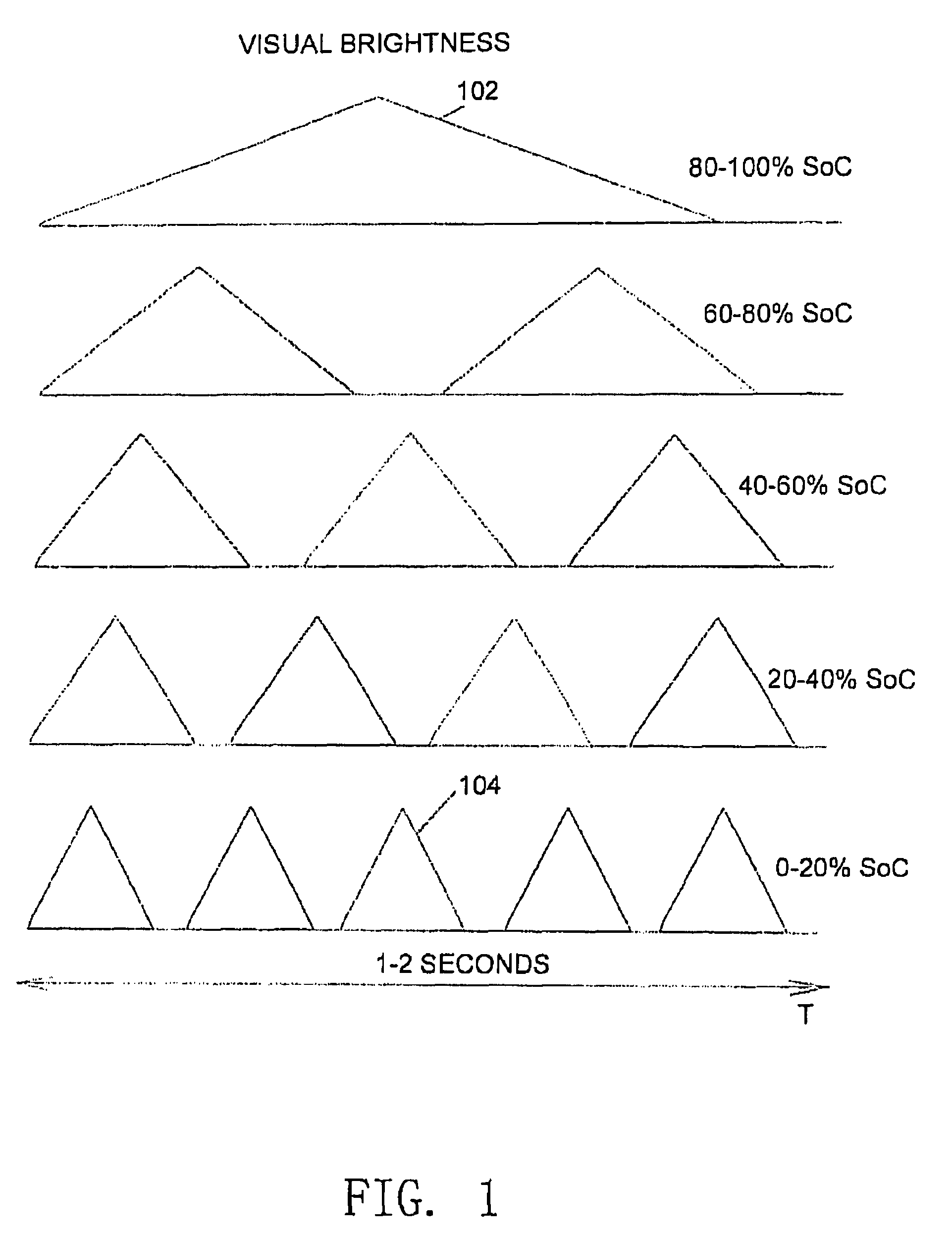
[0022]FIG. 1 shows graphs that correspond to the changing visual brightness of an LED responsive to a variation of a battery state of charge. The LED is associated with an electronic device having a battery as a power source. The changing speed of visual brightness herein is also referred to as blinking frequency. In one embodiment, the present invention uses only one LED to display a battery's State of Charge (SoC) by changing the blinking frequency. Fast blinking of a light source is usually associated with a warning or danger. To take advantage of this conditioned association, it is desirable that a fast visual brightness change of an LED be representative of the event of empty battery state. In other words, the battery state of charge (SoC) is preferably inversely proportional to the changing speed of visual brightness of the LED in one embodiment of the present invention. It can be easily seen from plot 102 in FIG. 1 that when the capacity of the battery is 80%˜100% of the full...


PUM


Abstract

A method and apparatus are provided to indicate battery capacity status. Different blinking frequencies of an LED correspond to different battery states of charge. Furthermore, the present invention provides a smooth visual brightness change of the LED by providing the appropriate LED current according to human eye characteristics.

Description

RELATED APPLICATIONS[0001]This application claims benefit of U.S. provisional patent application, Ser. No. 60 / 779,341, filed Mar. 3, 2006, which is hereby incorporated herein by reference in its entirety.FIELD OF THE INVENTION[0002]The invention relates to status indication techniques for electronic devices, more specifically, to status indication of battery capacity.BACKGROUND OF THE INVENTION[0003]A natural shortcoming of electronic devices that use batteries as a power source is battery capacity limitations. Unexpected power loss can cause data loss and other unexpected malfunctions. To avoid this, some electronic devices provide battery status indications (e.g. full battery status, empty battery status, or the level of available battery capacity in use) to inform users of battery status so that the users can take some action, such as saving data, before the battery depletes its energy and shuts down the system. Normally, one or more LEDs are used as an indicator to inform custom...

Claims


Application Information

Patent Timeline
Patent Type & Authority Patents(United States)
IPC IPC(8): G08B21/00
CPCG08B5/36G08B29/181
Inventor DU, STERLINGLIU, LIUSHENGKOKORIN, OLEKSANDR
Owner O2 MICRO INT LTD
Why Eureka
Try Eureka