

Micro generator system
a generator system and micro-generator technology, applied in the direction of generators/motors, machines/engines, nuclear engineering, etc., can solve the problems of inability to meet the existing demand for effectively powering microsystem applications, heavy conventional batteries, short-lived,
- Summary
- Abstract
- Description
- Claims
- Application Information
AI Technical Summary
Benefits of technology
Problems solved by technology
Method used
Image

Examples
Embodiment Construction
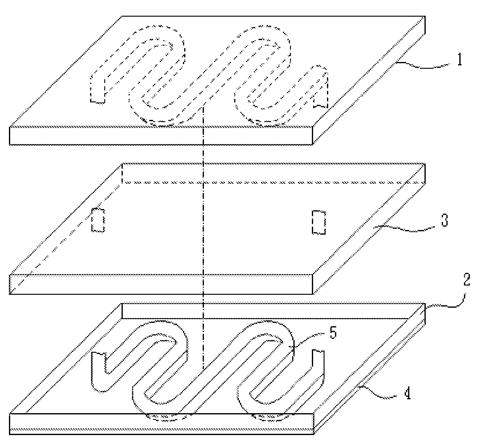
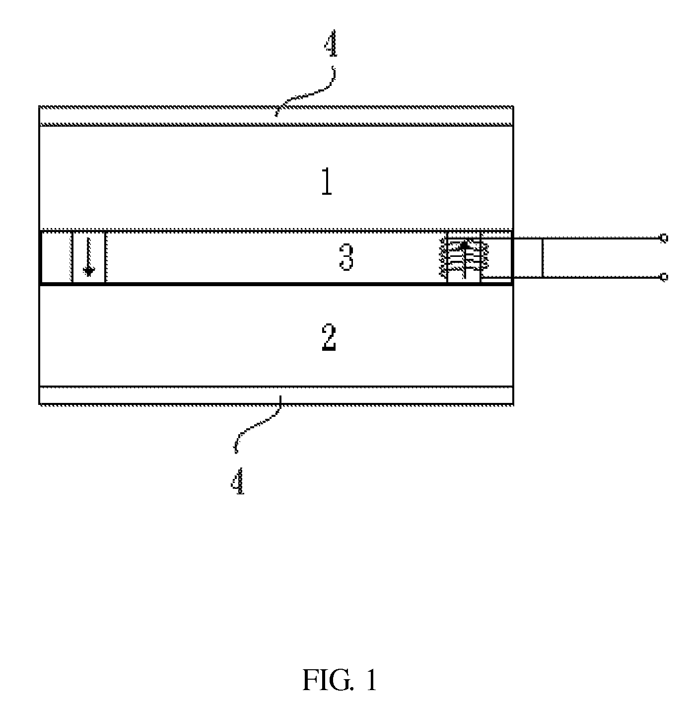
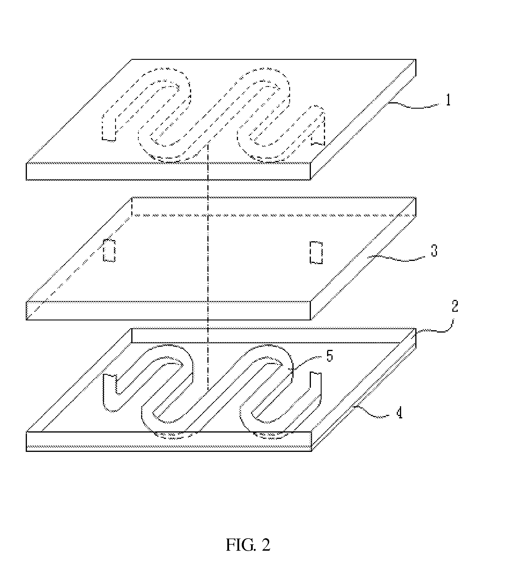
[0006]This present invention is directed to an automatic micro generator system which uses temperature difference (about 5˜10° C.) between the skin and the environment to allow an engine to drive microfluid flow and pass nano-magnetic particles within the microfluid through a coil to produce an induced electricity from magnetic flux. The electricity generated by this micro generator using temperature difference can be sustainably used in micro-devices such as hearing aids, pacemakers, and micro-transmitters. The micro generator is eco-friendly with a long product life cycle, which overcomes the inconvenience of frequent replacement when using conventional batteries, while offering a solution for recycling and environmental protection.
[0007]The micro generator of the present invention comprises a low-temperature-difference body heat engine and a coil wherein a thermal insulation zone is installed between the high-temperature zone and the low-temperature zone of the engine to prevent ...
PUM
 Abstract
Description
Claims
Application Information