Method and apparatus for manufacturing tyres for vehicle wheels

a technology for vehicle wheels and manufacturing methods, applied in the direction of tyre parts, transportation and packaging, other domestic articles, etc., can solve the problems of affecting the appearance affecting the quality of the finished product, so as to prevent or avoid the effect of stopping the sam

Active Publication Date: 2011-11-01
PIRELLI TYRE SPA
View PDF13 Cites 0 Cited by
  • Summary
  • Abstract
  • Description
  • Claims
  • Application Information

AI Technical Summary

Benefits of technology

[0018]The Applicant has therefore perceived the necessity to provide the mould with vent valves capable of preventing, or at least greatly reducing, blend seepage into the ducts of said valves and therefore avoid stoppage of same, as well as formation of the above mentioned threadlike outgrowths generally found in the known art embodiments.
[0019]The Applicant has found that the above mentioned problems can be eliminated or at least greatly reduced by arranging on the closing head of the valve, a region of engagement with the tyre blend in such a manner that, when the finished tyre is moved away from the inner surface of the mould, the tyre itself co-operates in this operation by exerting a pulling action on the closing head of the valve towards the closed position of the mould. In this way, opening of the mould helps in carrying out the possible separation of the closing head of the valve from the respective seat.
[0020]The Applicant has further found that it is advantageously possible to greatly limit the projection of the closure member head towards the inside of the moulding cavity and therefore, as a result, to remarkably reduce blend seepages at the inside of the valve duct even when the blend reaches said valve by its tangential movement along the holding walls of the moulding cavity, carrying out coupling between the valve seat and the closure member head of said valve in such a manner that, at least in the closed position, the closure member head keeps at least partly embedded in the mould wall.
[0021]The Applicant has further found that the above problems can be advantageously solved even when the closure member head keeps at least partly embedded in the mould wall also in the open position of the valve itself.

Problems solved by technology

Adoption of ducts passing through and opening into the moulding cavity however, involves a plurality of problems due to seeping of the green-tyre blend into the ducts themselves during the moulding step.
Alternatively, these threadlike outgrowths are not removed from the outer surface of the finished tyre and in this case they involve worsening of the aesthetic-qualitative level of said tyre.
This situation is particularly disadvantageous because, due to the presence of this blend, the closing head and the wall of the duct tend to glue together until, after repeated cycles, a definitive stoppage of the valve occurs and, as a result, said valve needs to be replaced in order to restore a correct evacuation of the air from the moulding cavity.
This aspect is particularly disadvantageous because in some regions of the mould, in particular at the mould regions designed to form the tyre shoulders, the blend tends to flow tangential to the mould wall and to approach the valve head in a lateral direction relative to said valves.
The Applicant has further noticed that the presence of blend interposed between the closing head and the seat of the valve compromises a correct closure of the valve itself and brings to formation of faults on the finished product.
Repetition of this phenomenon during subsequent vulcanisation cycles further involves an increasingly greater storage of cured blend within the valve, so that, cycle after cycle, an unavoidable stoppage of the valve itself will be caused.
Finally, the Applicant has ascertained that the side thrust of the blend on the closing head of the valve can cause misalignment of the valve stem relative to the duct in which the valve slides.

Method used


Image

  • Method and apparatus for manufacturing tyres for vehicle wheels
  • Method and apparatus for manufacturing tyres for vehicle wheels
  • Method and apparatus for manufacturing tyres for vehicle wheels

Examples


Embodiment Construction

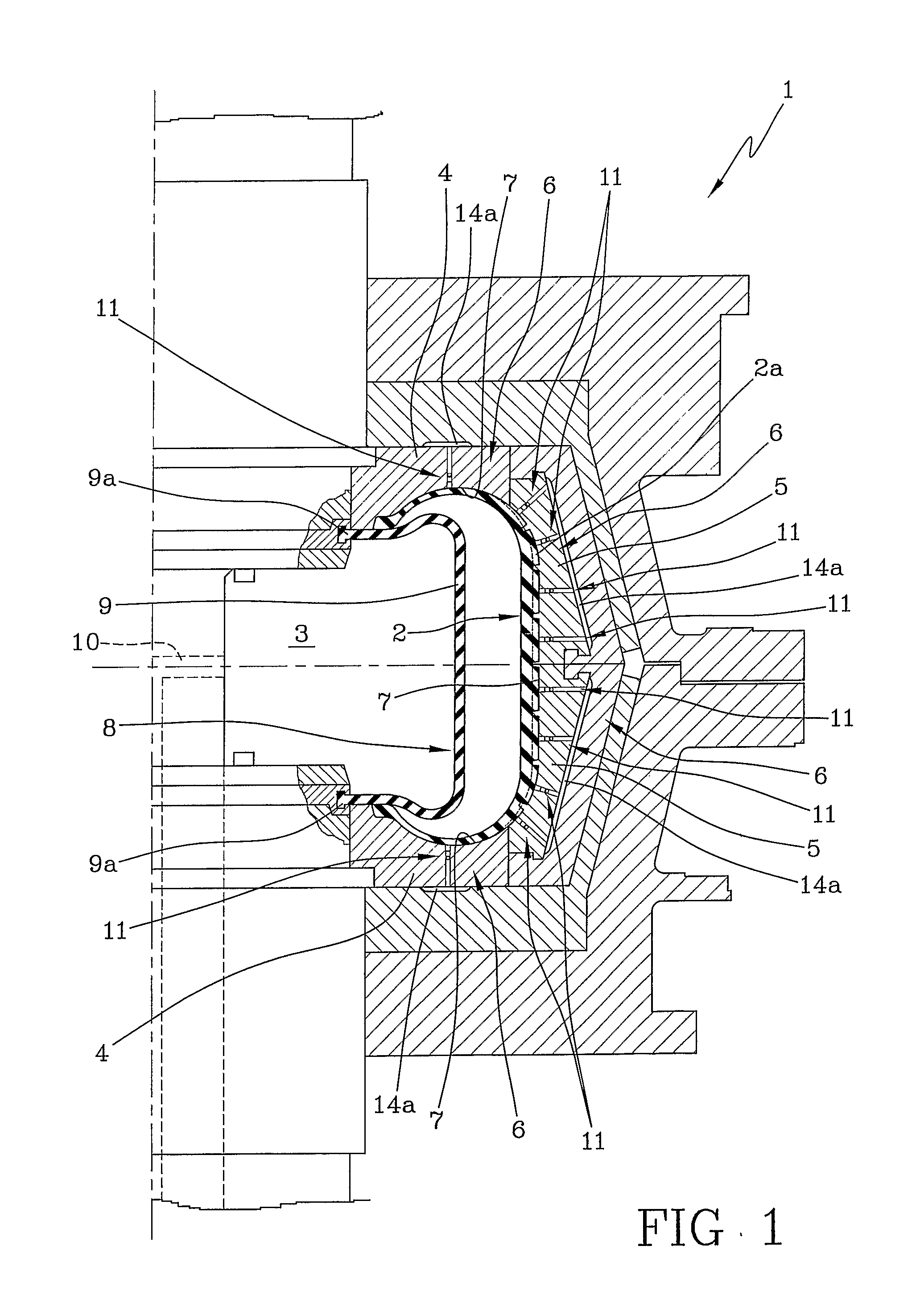
[0040]With reference to FIG. 1, a vulcanisation mould belonging to an apparatus for manufacturing tyres for vehicle wheels in accordance with the present invention has been generally denoted at 1.

[0041]This apparatus generally comprises devices adapted to form a green tyre 2 and devices capable of transferring the green tyre 2 into a moulding cavity 3 of the vulcanisation mould 1. Said tyre-forming and transferring devices are neither shown nor further described as they can be made in any convenient manner.

[0042]As shown in FIG. 1, the vulcanisation mould 1 has a pair of axially opposite cheeks 4 and a plurality of circumferential sectors 5 that, when the mould is closed, define the holding walls 6 of the moulding cavity 3. The holding walls 6 delimit an inner surface 7 of the moulding cavity 3 the shape of which matches the final conformation to be given to the tyre. The green tyre 2, once closed in mould 1, is pressed against the holding walls 6 by a suitable device 8. Subsequentl...


PUM

PropertyMeasurementUnit
embedding distanceaaaaaaaaaa
separation distanceaaaaaaaaaa
embedding distanceaaaaaaaaaa

Abstract

In a method for manufacturing tyres for vehicle wheels, a green tyre, once formed, is transferred into a vulcanisation mould and pressed against the holding walls of a moulding cavity. Concurrently with the pressing step, a fluid present between the green tyre and the holding walls is evacuated through vent valves. The tyre is brought into contact with the closing head of each valve so as to push it toward a closed position of the valve itself. The closing head has a distal portion facing the moulding cavity and includes at least one grip element for the tyre blend, so that the closure member is pulled toward the open position while the moulded and cured tyre is moved away from the inner surface of said moulding cavity.

Description

CROSS REFERENCE TO RELATED APPLICATION[0001]This application is a national phase application based on PCT / IT2004 / 000731, filed Dec. 28, 2004, the content of which is incorporated herein by reference.BACKGROUND OF THE INVENTION[0002]1. Field of the Invention[0003]The present invention relates to a method and an apparatus for manufacturing tyres for vehicle wheels.[0004]2. Description of the Related Art[0005]Generally, in tyre manufacture for vehicles wheels, subsequently to a step of building a green tyre through assembling of respective components of elastomeric material some of which are provided with suitable reinforcing structures, a moulding and curing treatment is provided to be carried out to the aim of causing structural stabilisation of the tyre through cross-linking of the elastomeric components of same and, as generally required, of impressing a desired tread pattern into the tyre itself, as well as possible distinctive graphic marks at the tyre sidewalls.[0006]To this aim...

Claims


Application Information

Patent Timeline
Patent Type & Authority Patents(United States)
IPC IPC(8): B29C35/00B29C35/02
CPCB29C33/10B29D30/0606B29L2030/00B29D2030/0617B29D30/08
Inventor CAZZANTI, STEFANOBALINI, ALFREDO
Owner PIRELLI TYRE SPA
Why Eureka
Try Eureka