Mechanism of fastening detachable electronic device to DIN rail

a technology of electronic devices and din rails, which is applied in the direction of electrically conductive connections, coupling device connections, electrical apparatus construction details, etc., can solve the problems of non-standard rail types, damage to detachable electronic devices b>1/b>, and failure to mount detachable electronic devices to din rails

Active Publication Date: 2011-11-22
DELTA ELECTRONICS (THAILAND) PUBLIC CO LTD
View PDF1 Cites 22 Cited by
  • Summary
  • Abstract
  • Description
  • Claims
  • Application Information

AI Technical Summary

Problems solved by technology

Due to deformation, the DIN rail 2 may be damaged or even fail to be reusable.
In addition, if the external force is improperly exerted, the DIN rail 2 possibly has a breakdown and thus the detachable electronic device 1 fails to be mounted to the DIN rail 2.
Although standardized DIN rails are typically used for mounting electrical components, different, non-standard rail types are becoming more widespread in use.
In other words, the DIN rail 2 is not suitable to be vertically arranged because the detachable electronic device 1 is likely loosened or detached from the DIN rail 2 in a case of abrupt impact.
Under this circumstance, the safety and the stability of the detachable electronic device 1 are impaired.

Method used


Image

  • Mechanism of fastening detachable electronic device to DIN rail
  • Mechanism of fastening detachable electronic device to DIN rail
  • Mechanism of fastening detachable electronic device to DIN rail

Examples


Embodiment Construction

The present invention will now be described more specifically with reference to the following embodiments. It is to be noted that the following descriptions of preferred embodiments of this invention are presented herein for purpose of illustration and description only. It is not intended to be exhaustive or to be limited to the precise form disclosed.

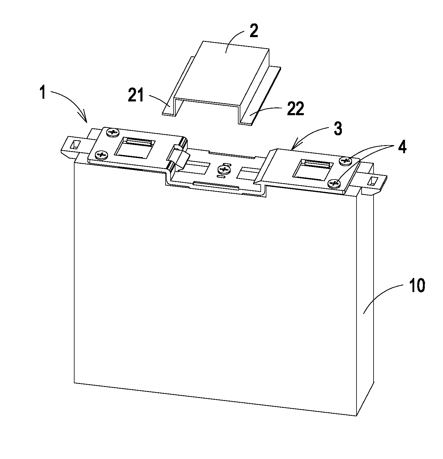
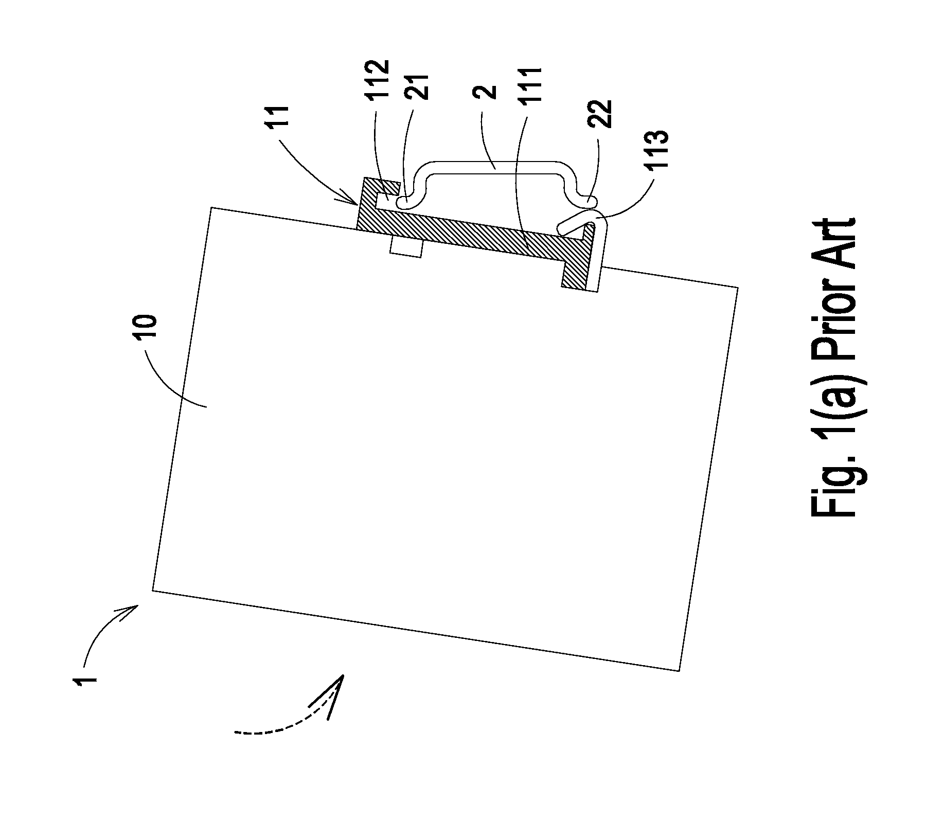
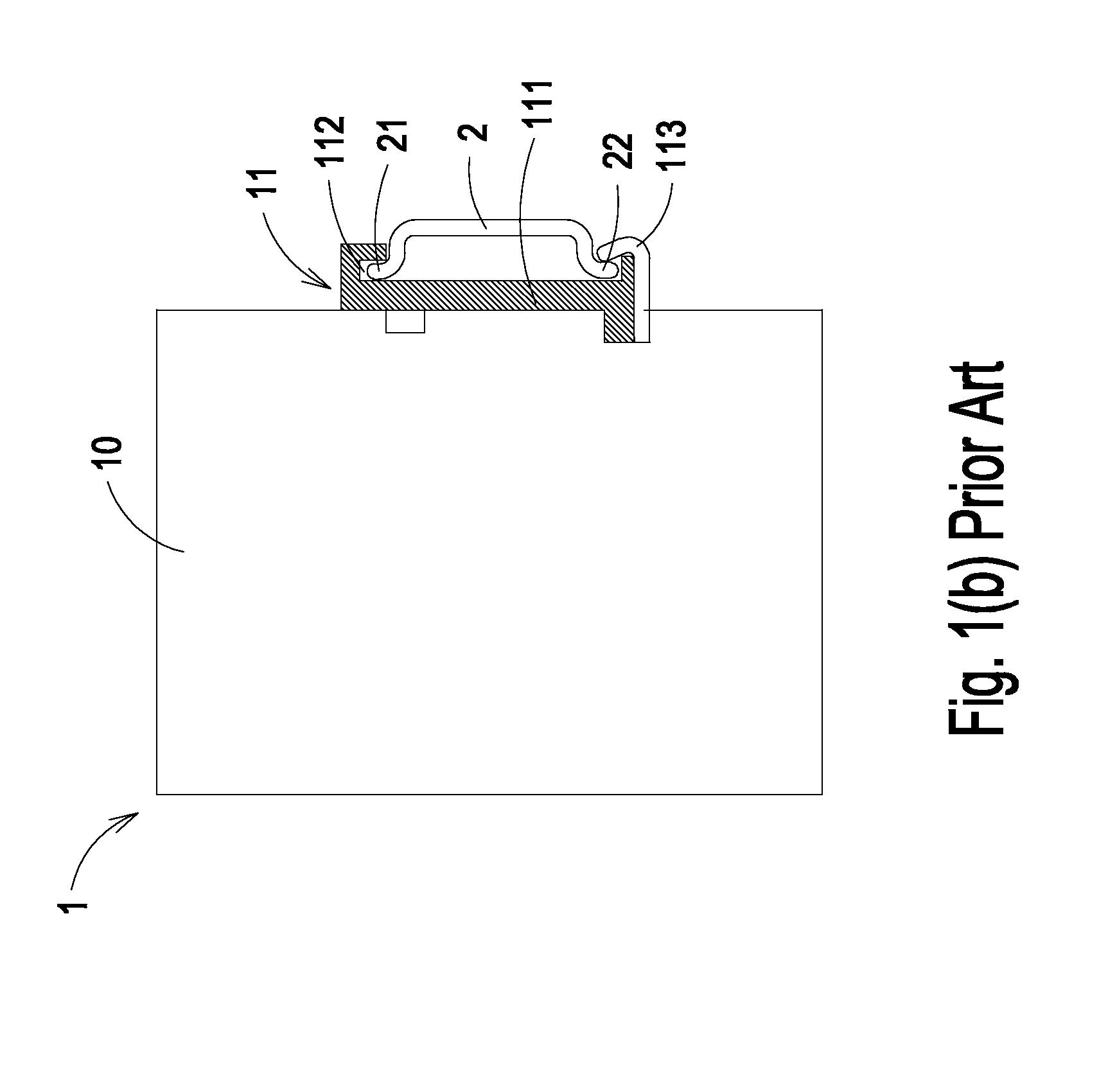
Referring to FIG. 2(a), a schematic detachable electronic device to be mounted to a DIN rail according to a first preferred embodiment of the present invention is illustrated. The detachable electronic device 1 includes a main body 10 and a fastening mechanism 3. The fastening mechanism 3 is fixed on the main body 10 via at least a screwing element 4. By engagement between the fastening mechanism 3 and the extending edges 21, 22 of the DIN rail 2, the main body 10 of the detachable electronic device 1 is mounted to the DIN rail 2.

Hereinafter, a first variant of the fastening mechanism 3 will be illustrated in more details with referenc...


PUM


Abstract

A fastening mechanism for fastening a detachable electronic device onto a DIN rail includes a frame, a first slab member and a first resilient element. The frame includes a base, a first extension part and a second extension part. The first extension part and the second extension part are arranged at bilateral sides of the base. A first perforation is formed between the first extension part and the base. The first slab member is movable along the bottom surface of the first extension part and has an end penetrating through the first perforation to be disposed over the base. The first resilient element is coupled to the first slab member and exerts a clamping force for claming a first extending edge of the DIN rail between the first slab member and the base.

Description

FIELD OF THE INVENTIONThe present invention relates to a fasting mechanism, and more particularly to a mechanism for fastening a detachable electronic device onto the DIN rail.BACKGROUND OF THE INVENTIONElectronic device housings are frequently mounted to a DIN rail. For example, power supply apparatuses are usually detachably mounted to a DIN rail in a manner which resists unintentionally loosening the housing from the rail but permits easy removal for repair or replacement. In this regard, the housing of the electronic device has a mechanism for attaching the electronic device to the DIN rail.Referring to FIG. 1(a), a schematic exploded view of a detachable electronic device and a DIN rail is illustrated. The housing 10 of the detachable electronic device 1 includes a fastening mechanism 11. The fastening mechanism 11 includes a bracket 111. The bracket 111 has a recess 112 for receiving the first extending edge 21 of the DIN rail 2. In response to an external force applying on th...

Claims


Application Information

Patent Timeline
Patent Type & Authority Patents(United States)
IPC IPC(8): H01R13/66
CPCH02B1/052H01R9/2608
Inventor LIM, CHOO SOOPHUMCHAI, CHAISRI
Owner DELTA ELECTRONICS (THAILAND) PUBLIC CO LTD
Why Eureka
Try Eureka