
Pallet jack system and method for the transportation of stackable packaged goods pallets

a pallet jack and packaged goods technology, applied in the field of pallet jacks, can solve the problems of scuffing polished floors, dangerous operation of pallet jacks, and ineffective use of these types of pallet jacks outsid

Active Publication Date: 2011-12-13
COCA-COLA BOTTLING CO UNITED INC
View PDF21 Cites 26 Cited by
  • Summary
  • Abstract
  • Description
  • Claims
  • Application Information

AI Technical Summary

Benefits of technology

[0013]It is a specific object of the invention to provide a pallet jack that can be used in substantially rough or non-smooth terrain.
[0072]According to the sixth aspect of the present invention the strap comprises: a retractable strap configured to retract into a strap container such that the retractable strap is substantially prevented from inadvertently coming into contact with other objects, and wherein each of the left and right the rear wheels comprises: a locking wheel that can be manually locked to substantially prevent inadvertent rolling of the pallet jack.

Problems solved by technology

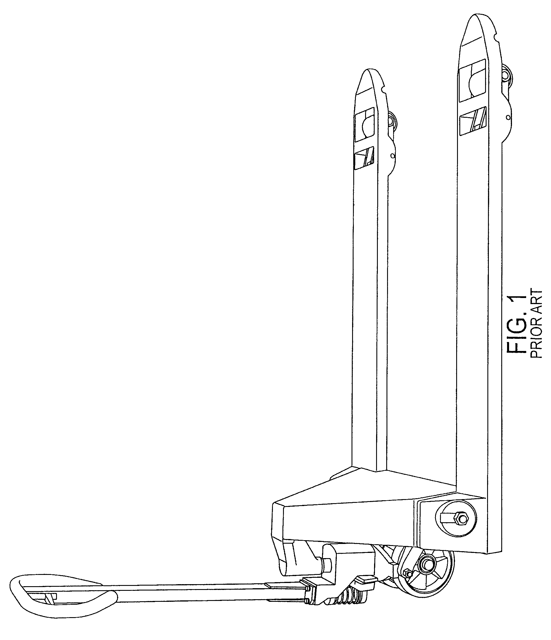
Using these types of pallet jacks outside, on the rough terrain of a gravel parking lot would be ineffective at best, and possibly dangerous because of their instability in that type of environment.
Furthermore, if the dimensions of the pallet the pallet jack were carrying was such that its width exceeds the width of the tines, and the pallet's length was longer than that of the tines, then again the pallet jack could be dangerous to operate.
Further still, using the prior art jack as shown in FIG. 1 inside a retail environment, such as a convenience store, could scuff the polished floors because of the type of wheels that are typically used.
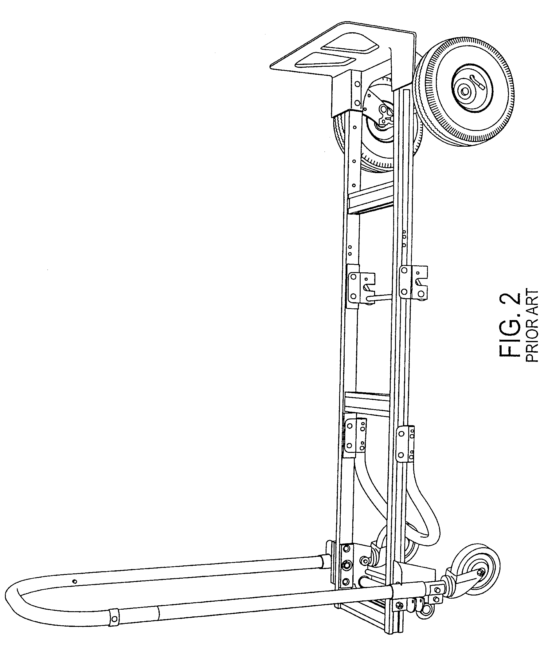
As can be seen, however, these types of devices lack any type of lifting mechanism, the rear wheels that pivot are too small for rough terrain (such as gravel parking lots) and the amount of goods they can lift are limited by structural limitations of the device.
Furthermore, to use such a device shown in FIG. 2, a user will have to load each item and then unload each item.
This type of repetitious activity can lead to repetitive motion injuries, accidents and thus increases costs for the manufacturer / distributor of the goods / products delivered by the device.

Method used


Image

  • Pallet jack system and method for the transportation of stackable packaged goods pallets
  • Pallet jack system and method for the transportation of stackable packaged goods pallets
  • Pallet jack system and method for the transportation of stackable packaged goods pallets

Examples


first embodiment

[0170]Referring to FIGS. 3, and 7-11, strap 50 is shown. Straps 50a, b (left and right sides) enable an operator to even more securely retain a loaded pallet 62 to pallet jack 100 when loaded onto and moved by pallet jack 100. Straps 50a, b are configured to operate similarly to seat belts in that they buckle together and can be tightened to secure loaded pallet 62 to pallet jack 100. Accordingly, strap 50a includes a receptacle, and strap 50b includes a buckle plug (or visa-versa). According to another embodiment of the present invention, straps 50a, b can be replaced with straps 51a, b that are retractable into a strap storage container (See FIG. 29). Straps 51a, b can also have a buckle receptacle and buckle jack, and can be tightened similarly to straps 50a, b. Alternatively, as shown in FIG. 29, strap 51 comprises a single length of retractable belt that has a loop at the extendable end that can be located on a strap post 78 as shown in FIG. 29. For security, clamp 76 is added ...

fourth embodiment

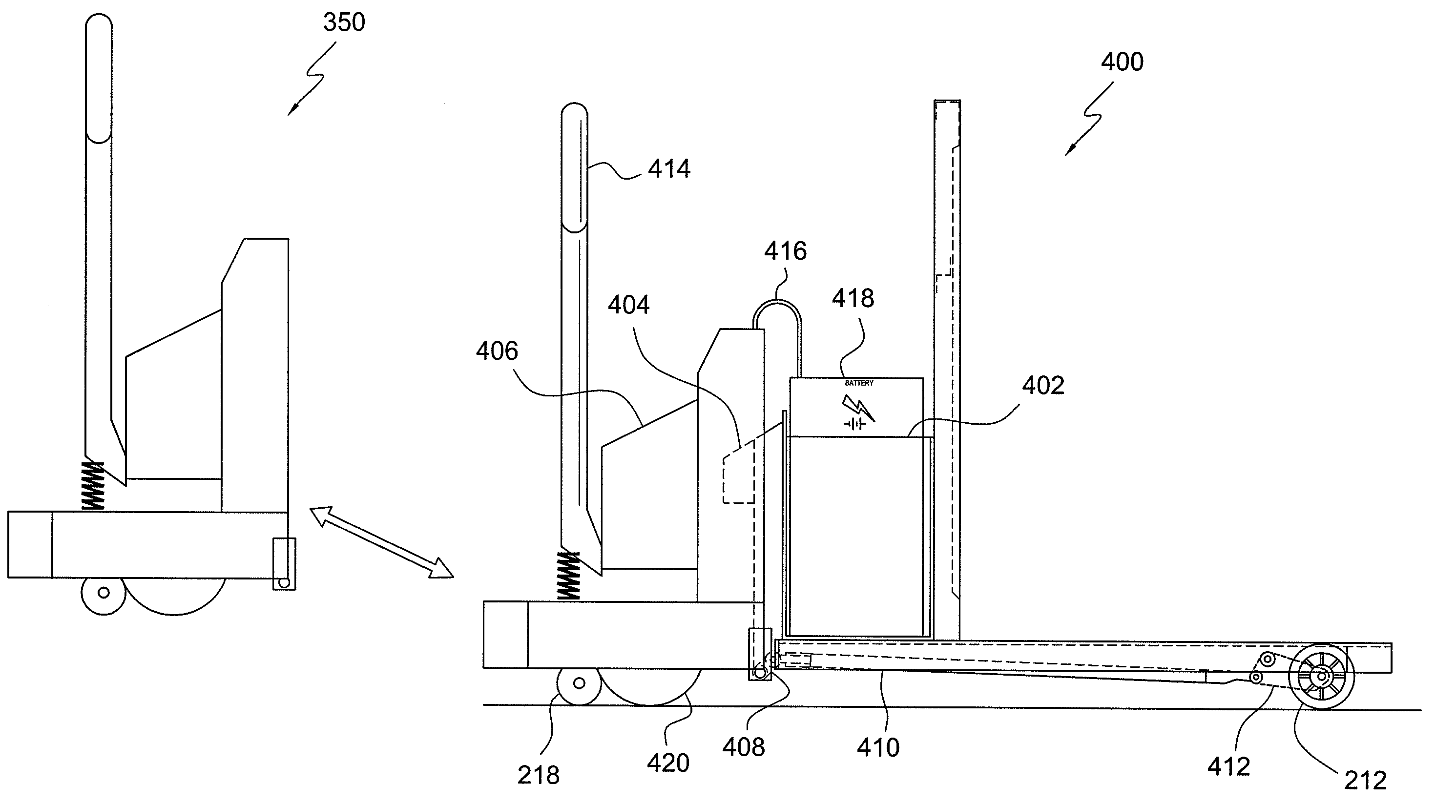
[0192]FIG. 38 illustrates a right side view of pallet jack 400 FIG. 39 illustrates a top view of pallet jack 400 as shown in FIG. 38, and FIG. 40 illustrates a front view of pallet jack 400 as shown in FIG. 38. Pallet jack 400 is substantially similar in appearance to pallet jacks 200, and 300, with the adaptation of energized lift and motive assembly 350, as shown in FIGS. 38-40. However, as those of ordinary skill in the art can appreciate, pallet jack 400 incorporates all the novel features of pallet jack 100 as described herein, and pallet jack 100 can be used with energized lift and motive assembly 350 in order to achieve the same benefits that will be apparent from the discussion below.

[0193]Energized lift and motive assembly 350 can be powered, as those of ordinary skill in the art an appreciate, by either a fossil fuel motor (i.e., natural gas, propane gas, gasoline, diesel, among other fossil fuel types), man-made chemical motors, or by an electrical motor, wherein the ele...


PUM


Abstract

A motorized pallet jack comprises one or more motors that can propel the pallet jack and lift each of the tines. The pallet jack has three tines, and the center tine can be about 2 times the width of each of the left and right tines, though other widths of the center tine can also be implemented. Because the center tine is about twice the width of the left and right tines, two pallets, side-by-side, can be carried simultaneously with only three tines. A portion of the center tine (a right-most portion) and the right tine can have raised areas that enable an operator of the pallet jack to lift a right pallet that sits on the raised areas higher than the left pallet. The left pallet sits on the left tine and center tine without the raised areas (at a lower height). The operator of the pallet jack can place the left pallet in a first location without disengaging the tines from the right pallet, or without lowering the right pallet all the way to the ground (or a first location surface). Alternatively, the raised areas can be located on the left tine and the left-most portion of the center tine, in which case, the operator of the pallet jack can place the right pallet in a first location without disengaging the tines from the left pallet, or without lowering the left pallet all the way to the ground (or a first location surface).

Description

PRIORITY[0001]Pursuant to 37 C.F.R. §1.52(b)(2), this application claims priority as a Continuation-in-Part Application under 35 U.S.C. §120 to U.S. Non-provisional Patent Application entitled “A Pallet Jack System and Method for the Transportation of Stackable Packaged Goods Pallets” filed in the U.S. Patent and Trademark Office on Jan. 22, 2008, and assigned Ser. No. 12 / 017,652, the entire contents of which are expressly incorporated herein by reference.CROSS REFERENCE TO RELATED APPLICATIONS[0002]Related subject matter is disclosed in co-pending U.S. Non-provisional patent application Ser. No. 11 / 615,635, entitled “Stackable Packaged Goods Pallet”, filed on Dec. 22, 2006; in co-pending U.S. Non-provisional patent application Ser. No. 11 / 615,677, entitled “A Pallet Jack System And Method for the Transportation of Stackable Packaged Goods”, filed on Dec. 22, 2006; and in co-pending U.S. Non-provisional patent application Ser. No. 11 / 890,530, entitled “Stackable Packaged Goods Palle...

Claims


Application Information

Patent Timeline
Patent Type & Authority Patents(United States)
IPC IPC(8): B66F9/12
CPCB62B3/0606B62B3/0612B62B5/0006B62B5/0433B62B2203/22B62B2203/44
Inventor ELLINGTON, STANLEY CHARLES
Owner COCA-COLA BOTTLING CO UNITED INC
Learn More