Gated electrodes for electrolysis and electrosynthesis

a gated electrode and electrolysis technology, applied in the direction of electrochemical machining apparatus, energy input, metal-working apparatus, etc., can solve the problems of oxidation, metal cathodes are not efficient photocathodes, nano-structured coatings do not significantly improve performance, etc., to achieve the effect of enhancing these effects

Inactive Publication Date: 2012-04-03
RGT UNIV OF CALIFORNIA
View PDF7 Cites 6 Cited by
  • Summary
  • Abstract
  • Description
  • Claims
  • Application Information

AI Technical Summary

Benefits of technology

[0026]The present invention discloses a gated electrode structure for altering the electric charge, field and potential distribution in an electrolyte near at least one working electrode. This alteration of electric parameters may be achieved in the following ways. Any two electrodes may be used as anode and cathode with one or more additional electrode(s) being the gate electrode. Steady state or time varying voltages may be applied to achieve the desired action. Proximity of the electrodes will enhance these effects.
[0028]Applying an appropriate gate voltage relative to the working electrode modifies the electric charge density, field and potential at one or more surfaces of the working electrode and increases charge transfer between the working electrode and states in the electrolyte (for example, increases electron emission from the working electrode to states in the electrolyte), thereby facilitating electrochemical, electrolytic or electrosynthetic reactions. In one embodiment, the working electrode is a cathode, and a static or dynamic bias on the gate electrode affects the electric charge, field and potential distribution near the cathode. The gate electrode may be a counter electrode in some part of the gating cycle. The-relative bias may be floating, static or time varying.
[0031]The present invention also discloses a method for reducing overvoltages in electrochemical and photoelectrochemical cells, (or in electrochemical, electrolytic, or electrosynthetic reactions) by modifying the electric charge, field and potential in the electrolyte near the electrode (more specifically, in an interfacial region between an electrolyte and one or more electrodes). The modification may use appropriately spaced electrodes or a fringing field between a semiconductor and a Schottky contact or heterojunction. The field may be enhanced using a fringing field between the working electrode which is a Schottky contact and a semiconductor or heterojunction acting as a gate. With time varying bias, remote gating is also possible.

Problems solved by technology

Metal cathodes are not efficient photocathodes.
N-type semiconductors with lower doping have been used as photo-anodes but have problems with oxidation.
Because the band bending is controlled by the semiconductor|electrolyte junction (211), there are some drawbacks in the overall concept in both schemes:(a) the built-in voltage and field that bring about carrier separation are due to surface effects that are less reproducible, and the built-in voltage is lower than can be obtained with semiconductor homo-junctions or hetero-junctions made on a substrate with a certain bandgap,(b) the energy level for electron transfer to the hydronium ion is not optimized and results in an overvoltage, and(c) the electric field in the electrolyte next to the semiconductor|electrolyte interface is controlled by the surface charge and depletion charge in the semiconductor and is often controlled by the former.
However, the nano-structured coatings do not significantly improve performance, i.e. reduce overvoltage at high current densities, over that of conventional metal electrodes.
This is because none of the schemes listed above directly address the problem of altering the field and potential distribution in the electrolyte next to an electrode, and this is a parameter that needs investigation.

Method used


Image

  • Gated electrodes for electrolysis and electrosynthesis
  • Gated electrodes for electrolysis and electrosynthesis
  • Gated electrodes for electrolysis and electrosynthesis

Examples


Embodiment Construction

[0042]In the following description of the preferred embodiment, reference is made to the accompanying drawings which form a part hereof, and in which is shown by way of illustration a specific embodiment in which the invention may be practiced. It is to be understood that other embodiments may be utilized and structural changes may be made without departing from the scope of the present invention.

Overview

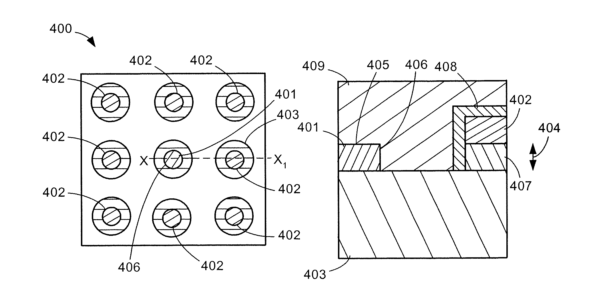
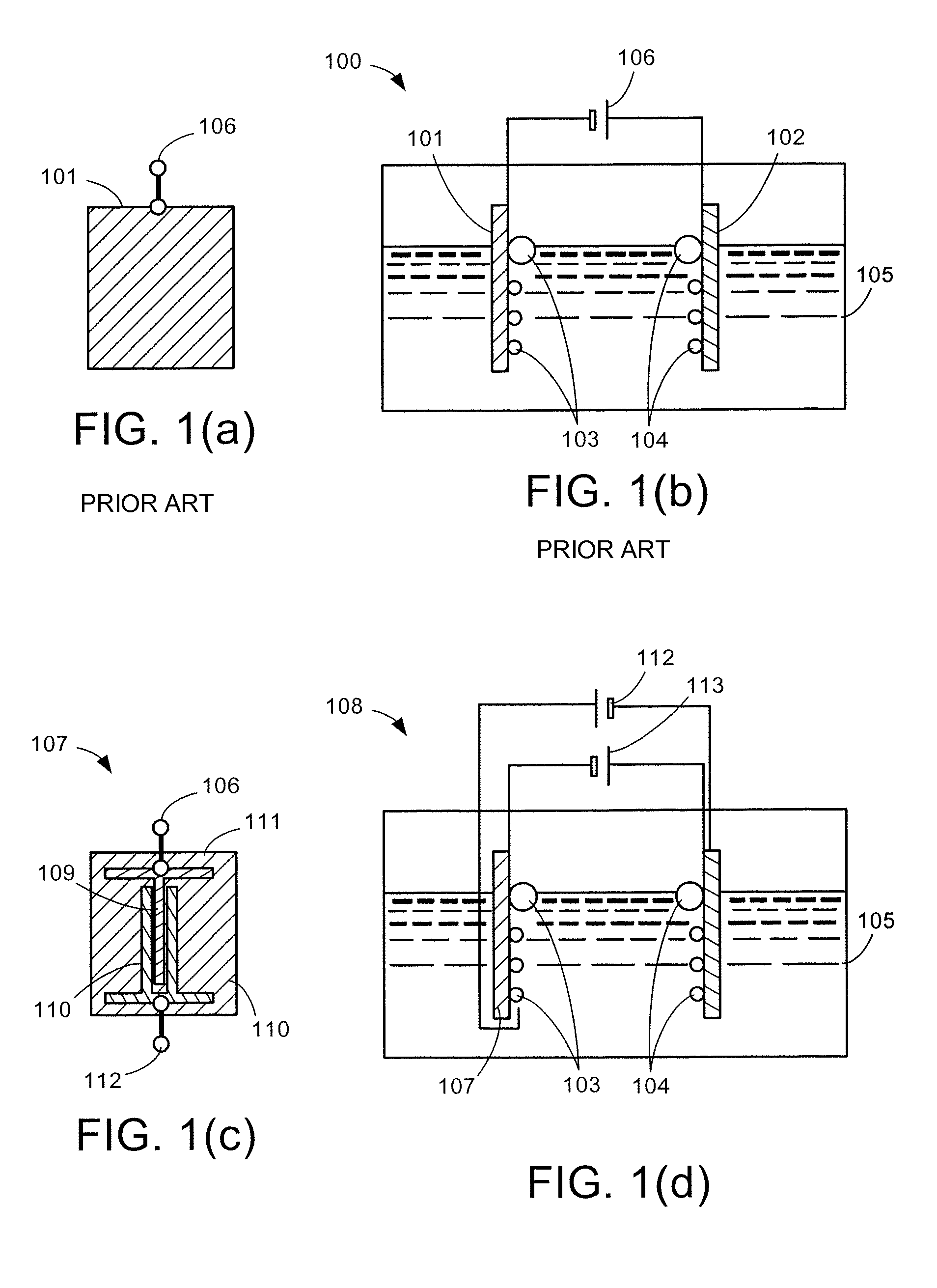
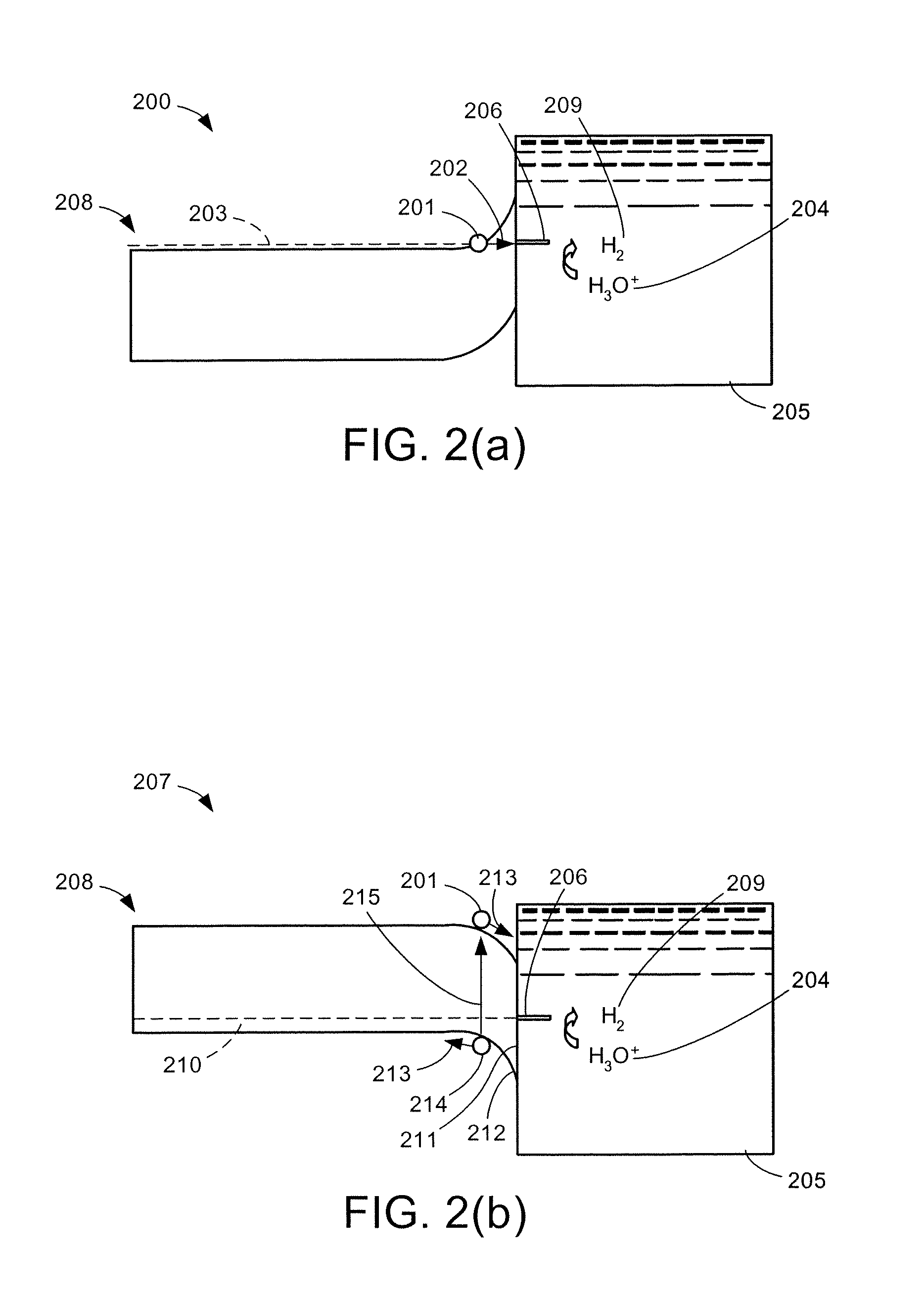
[0043]The present disclosure is about gated electrodes, wherein an electrode of the electrochemical or photo-electrochemical cell is replaced by an appropriate gated electrode that is comprised of two electrodes, with the gate electrode biased appropriately with respect to the working electrode. The dominant current flow at a gated electrode would be through the working electrode. The gate electrode, which is in proximity of the working electrode, is for the modification of electric charge, field and potential in the electrolyte next to the working electrode. Remote gating with time...


PUM

PropertyMeasurementUnit
temperatureaaaaaaaaaa
currentaaaaaaaaaa
electric chargeaaaaaaaaaa

Abstract

A gated electrode structure for altering a potential and electric field in an electrolyte near at least one working electrode is disclosed. The gated electrode structure may comprise a gate electrode biased appropriately with respect to a working electrode. Applying an appropriate static or dynamic (time varying) gate potential relative to the working electrode modifies the electric potential and field in an interfacial region between the working electrode and the electrolyte, and increases electron emission to and from states in the electrolyte, thereby facilitating an electrochemical, electrolytic or electrosynthetic reaction and reducing electrode overvoltage / overpotential.

Description

CROSS-REFERENCE TO RELATED APPLICATIONS[0001]This application claims the benefit under 35 U.S.C. Section 119(e) of the following co-pending and commonly-assigned U.S. patent application:[0002]U.S. Provisional Application Ser. No. 60 / 866,560 filed on Nov. 20, 2006, by Rakesh K. Lal, Likun Shen and Umesh K. Mishra, entitled “GATED ELECTRODES FOR ELECTROLYSIS AND ELECTROSYNTHESIS,”;[0003]which application is incorporated by reference herein.STATEMENT REGARDING FEDERALLY SPONSORED RESEARCH AND DEVELOPMENT[0004]This invention was made with Government support under Grant No. N00014-01-1-0764 awarded by the ONR MINE MURI program. The Government has certain rights in this invention.BACKGROUND OF THE INVENTION[0005]1. Field of the Invention[0006]This invention is related to designing gated electrode structures that aim to reduce overvoltages in electrochemical and photoelectrochemical cells by altering the field in the electrolyte near an electrode.[0007]2. Description of the Related Art[000...

Claims


Application Information

Patent Timeline
Patent Type & Authority Patents(United States)
IPC IPC(8): C25B9/04C25D17/00
CPCC25B11/0447C25B1/003C25B1/55C25B11/075Y02P20/133
Inventor LAL, RAKESH K.SHEN, LIKUNMISHRA, UMESH KUMAR
Owner RGT UNIV OF CALIFORNIA
Why Eureka
Try Eureka