Valve bridge having a centrally positioned hydraulic lash adjuster

a hydraulic lash adjuster and valve bridge technology, applied in the field of valve bridges, can solve the problems of poor emissions, valve guttering, exhaust valve not fully seating,

Active Publication Date: 2012-07-03
CATERPILLAR INC
View PDF36 Cites 46 Cited by
  • Summary
  • Abstract
  • Description
  • Claims
  • Application Information

AI Technical Summary

Problems solved by technology

Because a load is absent from the plunger, the hydraulic lash adjuster may pump-up, wherein the plunger may excessively protrude from the hydraulic lash adjuster, resulting in the exhaust valve not fully seating.
The partial opening of the exhaust valve may ultimately result in poor emissions and valve guttering.

Method used


Image

  • Valve bridge having a centrally positioned hydraulic lash adjuster
  • Valve bridge having a centrally positioned hydraulic lash adjuster
  • Valve bridge having a centrally positioned hydraulic lash adjuster

Examples


Embodiment Construction

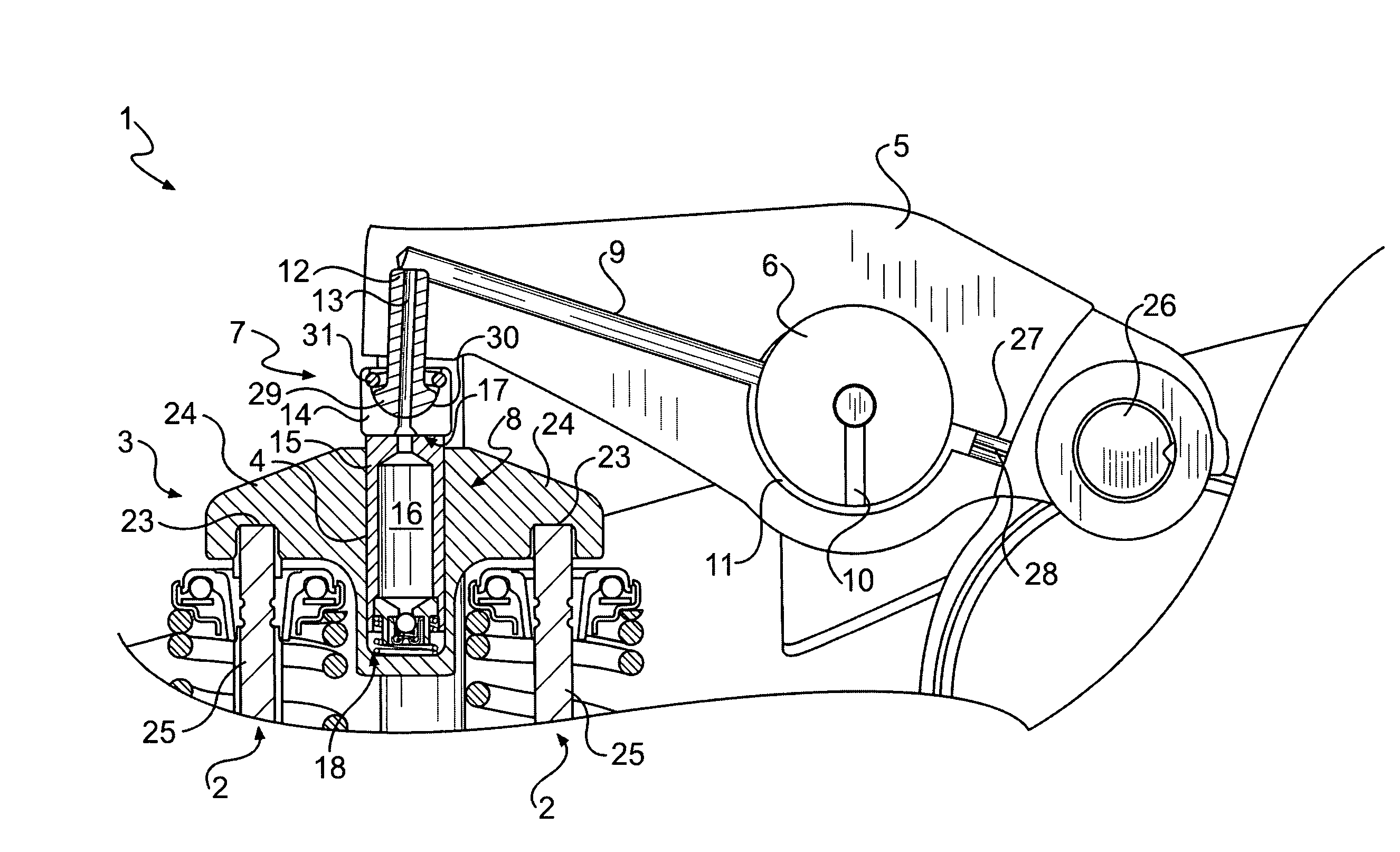
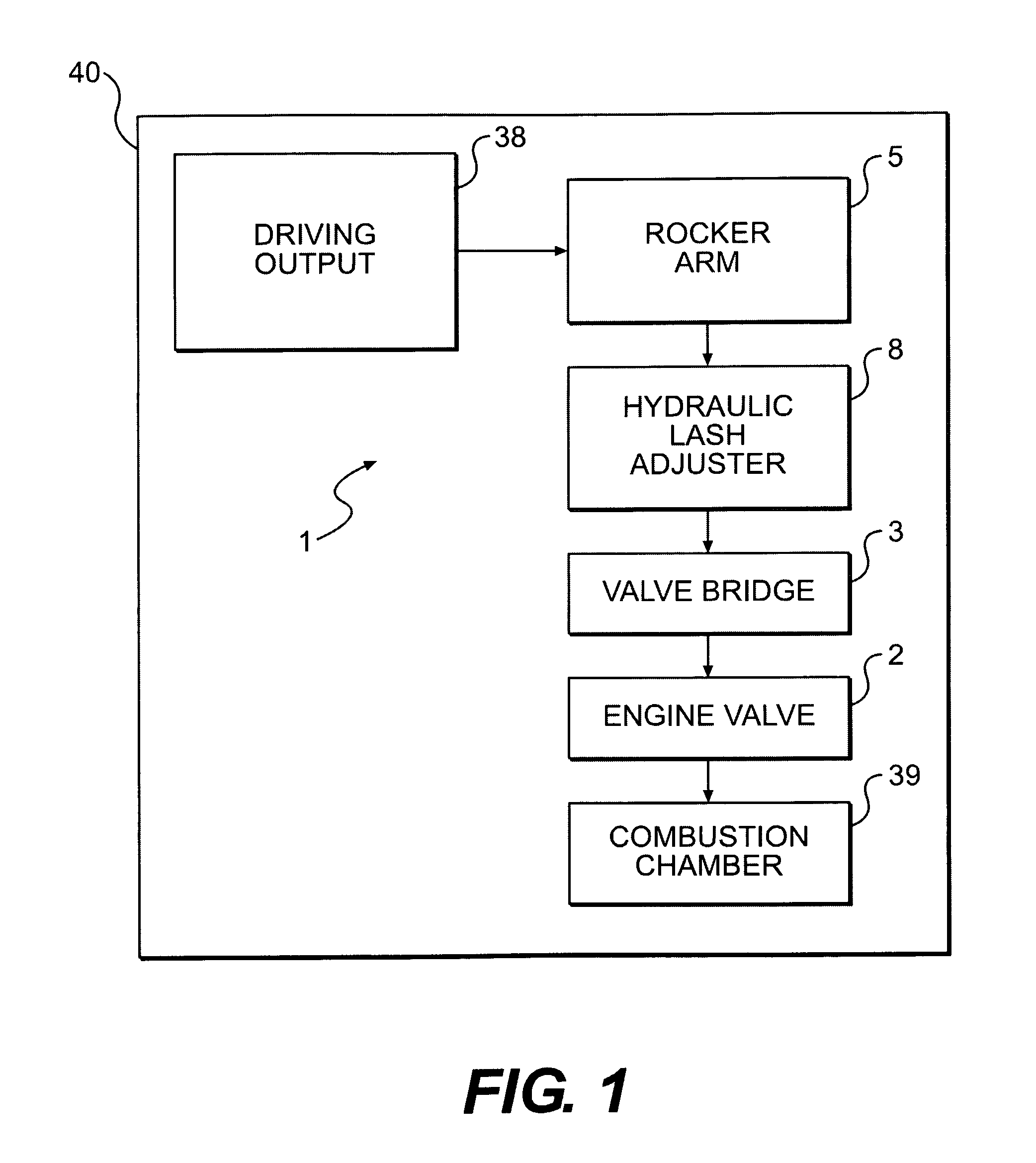
[0012]FIG. 1 diagrammatically illustrates an exemplary engine assembly 40. Engine assembly 40 may include at least one engine valve 2 and a compression braking system 1 configured to actuate engine valve 2. Actuation of engine valve 2 by compression braking system 1 may release compressed air from a compression stroke of a combustion cylinder 39 through engine valve 2 when a piston in combustion cylinder 39 nears a top-dead-center position.

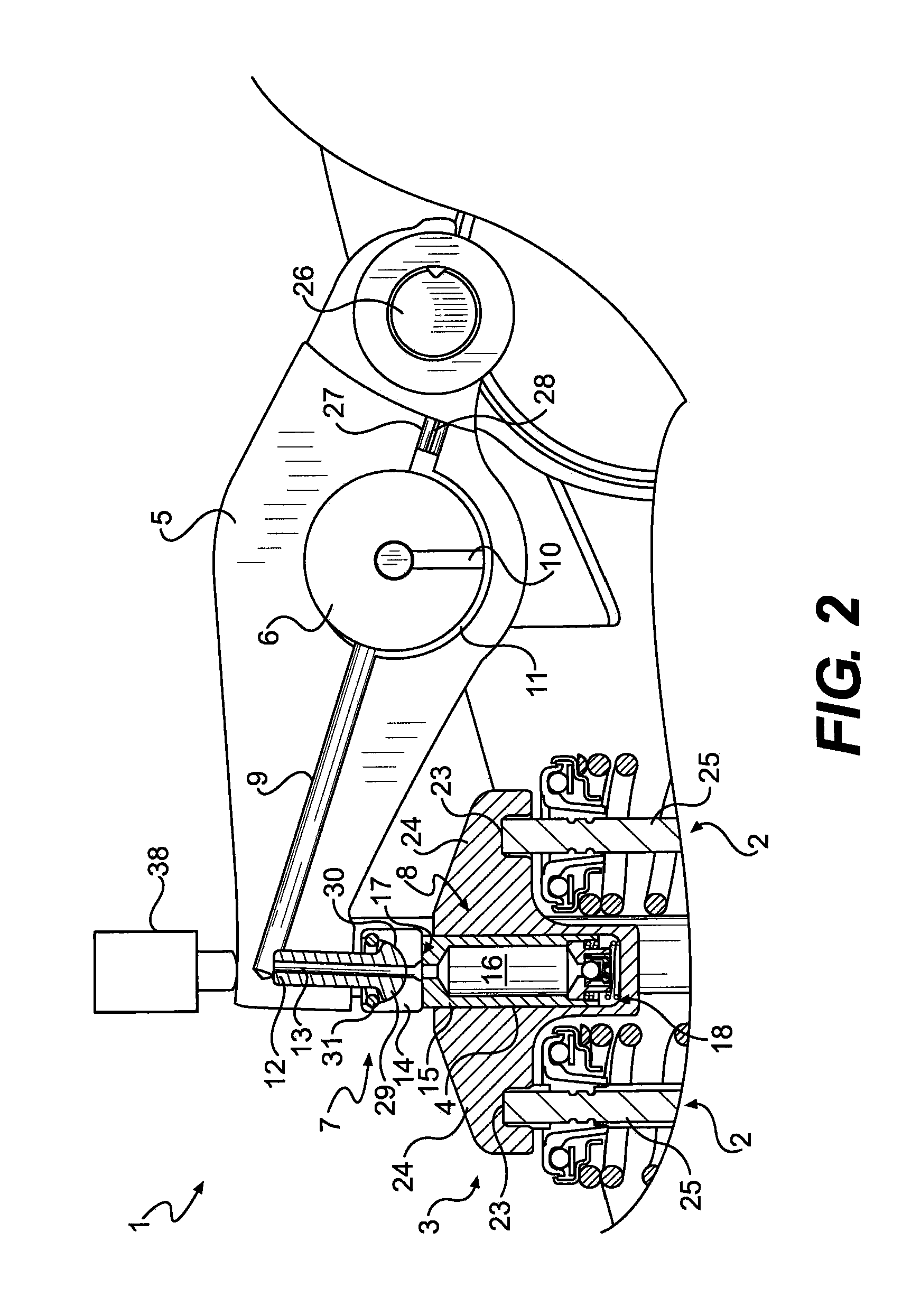
[0013]Compression braking system 1 may include a valve bridge 3 configured to engage engine valve 2, a hydraulic lash adjuster 8 associated with valve bridge 3, a rocker arm 5 configured to engage hydraulic lash adjuster 8, and a driving output 38 configured to actuate rocker arm 5. Driving output 38 may include a variety of known mechanism capable of actuating rocker arm 5 for compression braking events, such as a hydraulically controlled slave piston, and any conventional type of driving output may be employed.

[0014]FIG. 2 schematically illustra...


PUM


Abstract

A valve bridge configured to engage an engine valve is disclosed. The valve bridge includes a bridge cavity formed within a center portion of the valve bridge and including a bottom surface. A hydraulic lash adjuster is slidably disposed within the bridge cavity.

Description

TECHNICAL FIELD[0001]The present disclosure is directed to a valve bridge and, more particularly, to a valve bridge having a centrally positioned hydraulic lash adjuster.BACKGROUND[0002]Compression braking, or engine braking, may be employed to assist and supplement wheel brakes in slowing heavy machines, such as, on-highway trucks, construction machines, earthmoving machines, and the like. Compression braking may convert an internal combustion engine from a power generating unit into a power consuming air compressor. A compression braking system may actuate a cylinder exhaust valve and compressed air from the compression stroke of the engine is released through the cylinder exhaust valve when the piston in the cylinder nears the top-dead-center position. Generally, the exhaust valve is actuated by a rocker arm. The rocker arm is often operatively engaged with the exhaust valve by way of a valve bridge. The rocking motion of the rocker arm presses down on the valve bridge which in t...

Claims


Application Information

Patent Timeline
Patent Type & Authority Patents(United States)
IPC IPC(8): F01L1/26
CPCF01L1/14F01L1/18F01L1/181F01L1/245F01L1/26F01L13/06F01L13/065F16K15/044
Inventor LANGEWISCH, EDWIN HENRY
Owner CATERPILLAR INC
Why Eureka
Try Eureka