Retard roller and retard roller module having such retard roller
a retard roller and module technology, applied in the field of retard rollers, can solve the problems of affecting the efficiency of retard rollers, and affecting the use of retard rollers, and achieve the effect of convenient disassembly/assembling of retard roller modules
- Summary
- Abstract
- Description
- Claims
- Application Information
AI Technical Summary
Benefits of technology
Problems solved by technology
Method used
Image
Examples
first embodiment
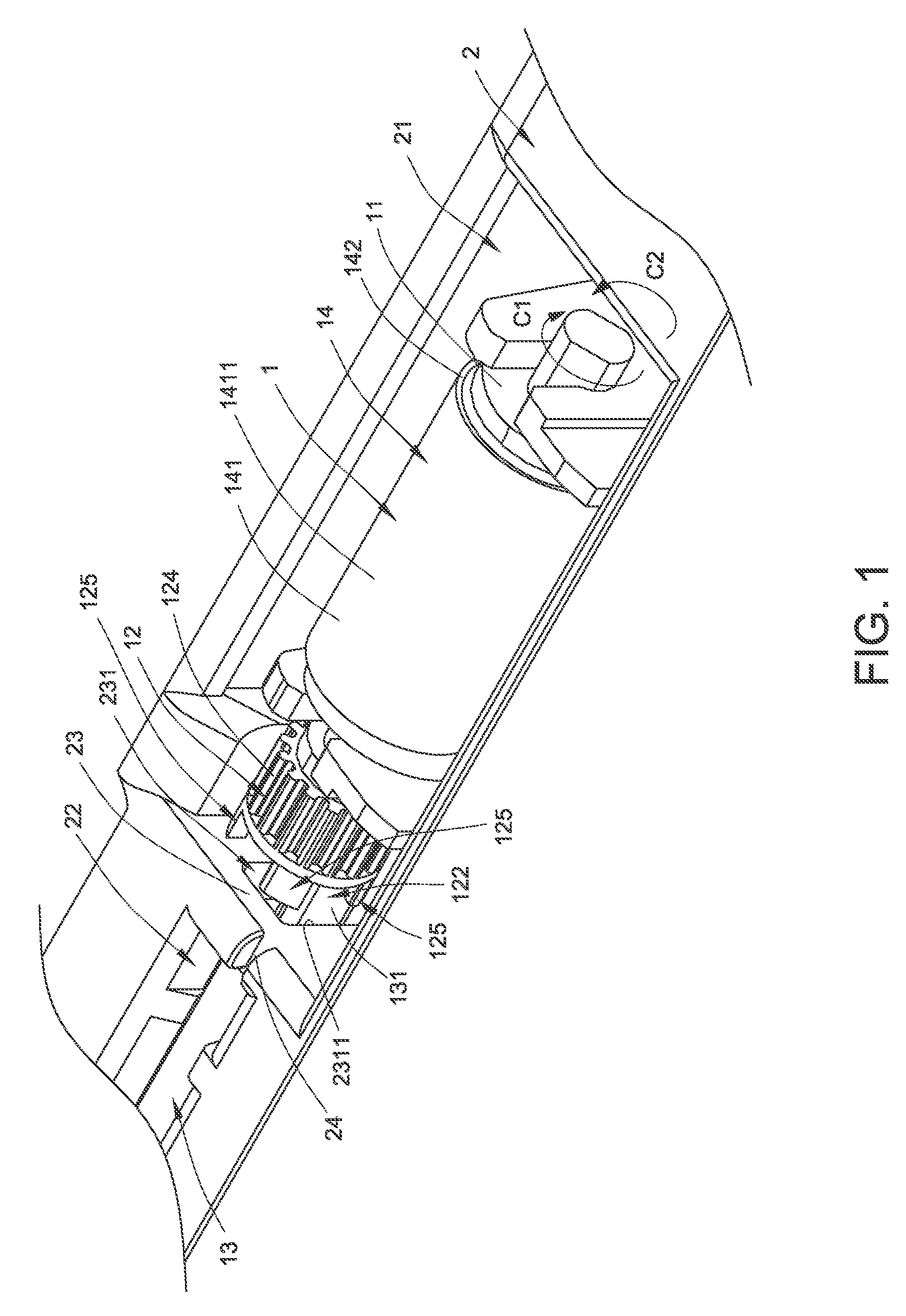
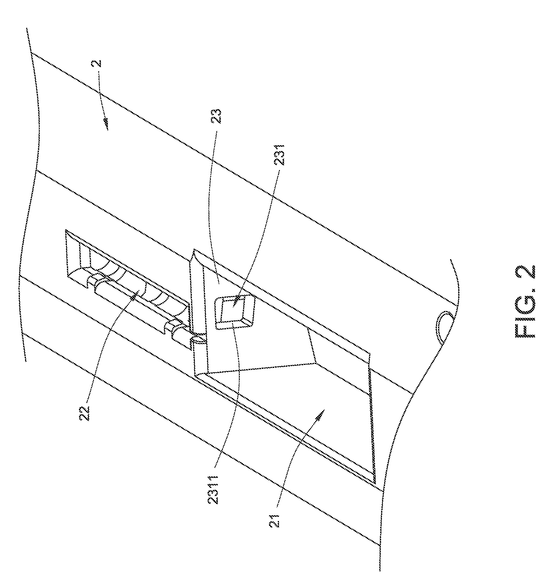
[0037]Hereinafter, the configurations and connecting relations of the components included in the retard roller 1 will be illustrated with reference to FIGS. 1 and 3. FIG. 3 is a schematic perspective view illustrating the retard roller according to the present invention. In the retard roller 1, the rotating shaft 11 is disposed within the retard roller receptacle 21. The switching wheel 12 is disposed beside the rotating shaft 11, connected to the rotating shaft 11, and synchronously rotated with the rotating shaft 11. The switching wheel 12 comprises a first locking region 121, a second locking region 122, a D-shaped pivotal hole 123, a saw-toothed surface 124 and plural locking posts 125. The rotating shaft 11 is penetrated through the D-shaped pivotal hole 123, so that the switching wheel 12 and the rotating shaft 11 are connected with each other and the switching wheel 12 is synchronously rotated with the rotating shaft 11. The saw-toothed surface 124 may provide a surface frict...
third embodiment
[0047]FIG. 10 is a schematic exploded view illustrating the retard roller module according to the present invention. Please refer to FIGS. 8 and 10 again. In the retard roller module 4, the module casing 40 is disposed within the retard roller module receptacle 51. The rotating shaft 41 is disposed within the module casing 40. The rotating shaft 41 has plural grooves 411 for receiving corresponding soft elements 45. The switching wheel 42 is disposed beside the rotating shaft 41, connected to the rotating shaft 41, and synchronously rotated with the rotating shaft 41. The switching wheel 42 comprises a first locking region 421, a second locking region 422, a D-shaped pivotal hole 423, a saw-toothed surface 424 and plural locking posts 425. The rotating shaft 41 is penetrated through the D-shaped pivotal hole 423, so that the switching wheel 42 and the rotating shaft 41 are connected with each other and the switching wheel 42 is synchronously rotated with the rotating shaft 41. The s...
PUM
 Abstract
Description
Claims
Application Information
 - R&D
- Intellectual Property
- Life Sciences
- Materials
- Tech Scout
- Unparalleled Data Quality
- Higher Quality Content
- 60% Fewer Hallucinations
Browse by: Latest US Patents, China's latest patents, Technical Efficacy Thesaurus, Application Domain, Technology Topic, Popular Technical Reports.
© 2025 PatSnap. All rights reserved.Legal|Privacy policy|Modern Slavery Act Transparency Statement|Sitemap|About US| Contact US: help@patsnap.com


