Supercharge Your Innovation With Domain-Expert AI Agents!

Retard roller and retard roller module having such retard roller

a retard roller and module technology, applied in the field of retard rollers, can solve the problems of affecting the efficiency of retard rollers, and affecting the use of retard rollers, and achieve the effect of convenient disassembly/assembling of retard roller modules

Inactive Publication Date: 2011-08-18
PRIMAX ELECTRONICS LTD
View PDF3 Cites 3 Cited by
  • Summary
  • Abstract
  • Description
  • Claims
  • Application Information

AI Technical Summary

Benefits of technology

[0007]A further object of the present invention provides an easily disassembled / assembled retard roller module.

Problems solved by technology

As the automatic document feeder is used for a long time, the separation pad is usually abraded, or even losses the function of separating documents.
As a consequence, the retard roller has a longer user life than the separation pad.
However, the retard roller and the separation pad have the similar drawbacks.
For example, there is no mechanism for prompting the abraded condition of the retard roller or the separation pad.
In a case that the retard roller or the separation pad is seriously abraded and has malfunction, the use of the retard roller or the separation pad may increase the possibility of causing the double feeding problem.
Until the user finds that the retard roller or the separation pad is seriously abraded, several double feeding events have occurred, and some documents are not successfully scanned.
The process of checking the double-fed documents is time-consuming.
In addition, it is also the time-consuming and troublesome to re-scan the double-fed documents.

Method used


Image

  • Retard roller and retard roller module having such retard roller
  • Retard roller and retard roller module having such retard roller
  • Retard roller and retard roller module having such retard roller

Examples


first embodiment

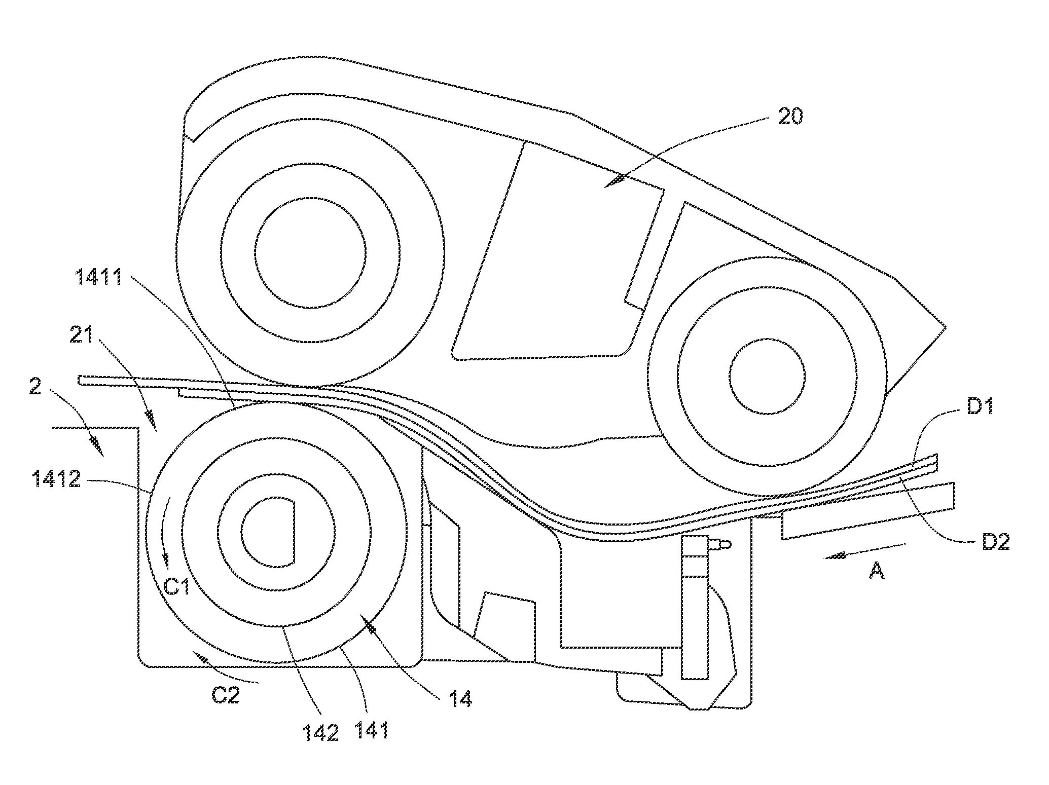
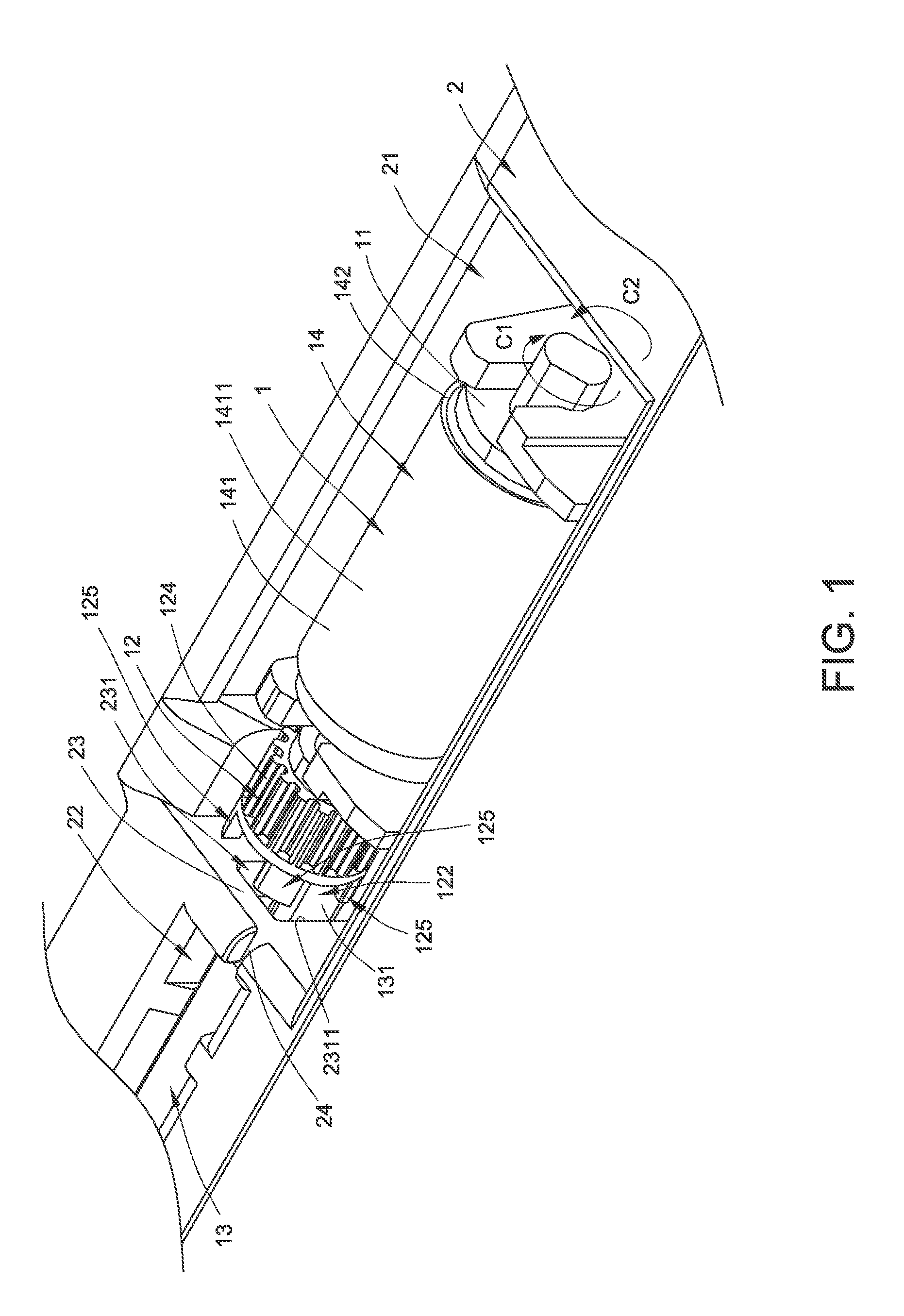
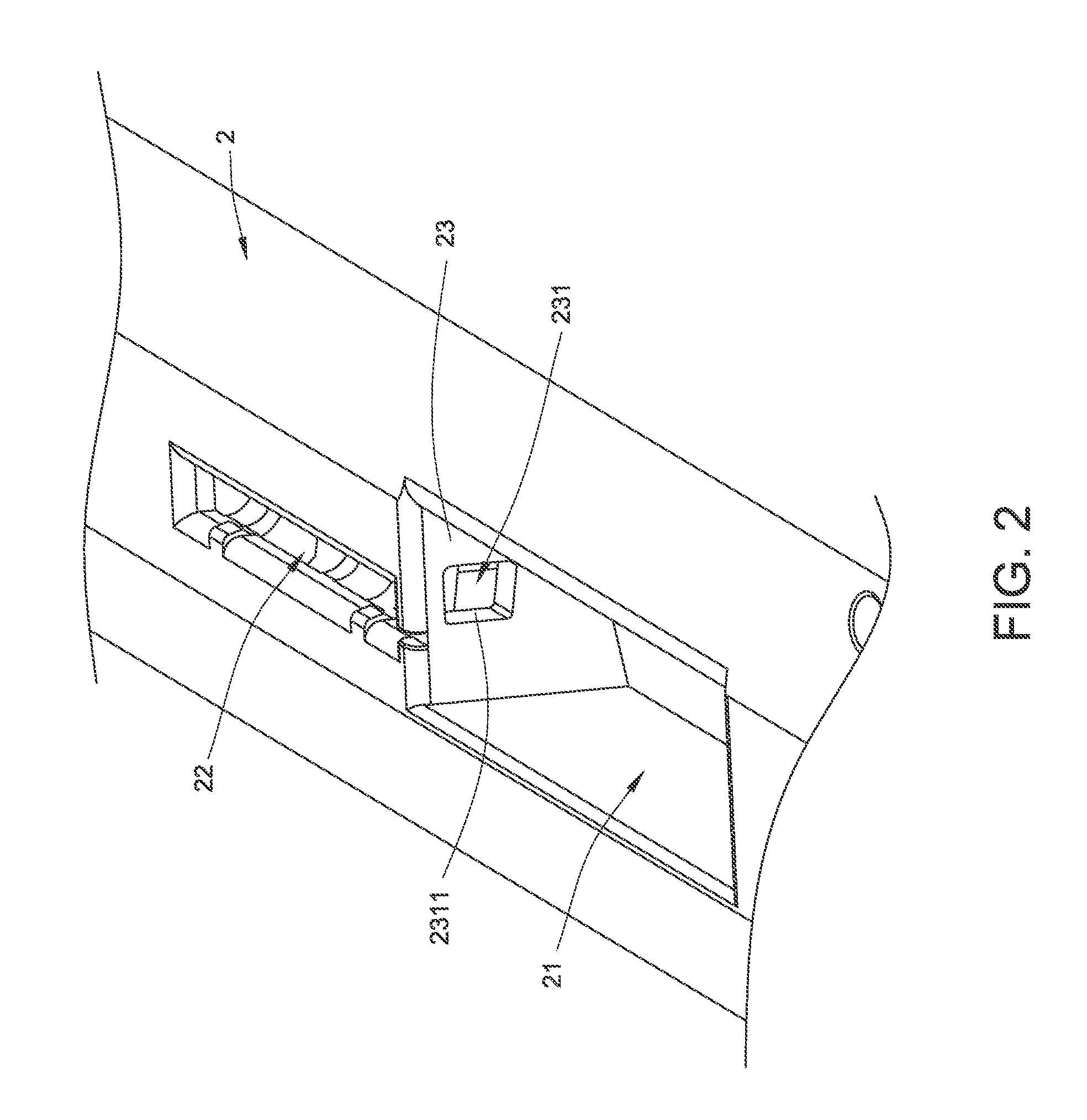
[0037]Hereinafter, the configurations and connecting relations of the components included in the retard roller 1 will be illustrated with reference to FIGS. 1 and 3. FIG. 3 is a schematic perspective view illustrating the retard roller according to the present invention. In the retard roller 1, the rotating shaft 11 is disposed within the retard roller receptacle 21. The switching wheel 12 is disposed beside the rotating shaft 11, connected to the rotating shaft 11, and synchronously rotated with the rotating shaft 11. The switching wheel 12 comprises a first locking region 121, a second locking region 122, a D-shaped pivotal hole 123, a saw-toothed surface 124 and plural locking posts 125. The rotating shaft 11 is penetrated through the D-shaped pivotal hole 123, so that the switching wheel 12 and the rotating shaft 11 are connected with each other and the switching wheel 12 is synchronously rotated with the rotating shaft 11. The saw-toothed surface 124 may provide a surface frict...

third embodiment

[0047]FIG. 10 is a schematic exploded view illustrating the retard roller module according to the present invention. Please refer to FIGS. 8 and 10 again. In the retard roller module 4, the module casing 40 is disposed within the retard roller module receptacle 51. The rotating shaft 41 is disposed within the module casing 40. The rotating shaft 41 has plural grooves 411 for receiving corresponding soft elements 45. The switching wheel 42 is disposed beside the rotating shaft 41, connected to the rotating shaft 41, and synchronously rotated with the rotating shaft 41. The switching wheel 42 comprises a first locking region 421, a second locking region 422, a D-shaped pivotal hole 423, a saw-toothed surface 424 and plural locking posts 425. The rotating shaft 41 is penetrated through the D-shaped pivotal hole 423, so that the switching wheel 42 and the rotating shaft 41 are connected with each other and the switching wheel 42 is synchronously rotated with the rotating shaft 41. The s...


PUM


Abstract

A retard roller and a retard roller module are provided. The retard roller is used in an automatic document feeder for providing a frictional force to separate plural documents from each other. Unidirectional rotation of the retard roller is permitted. Due to the unidirectional rotation, the contact surface of the retard roller can be switched. During the sheet-feeding process, the document is contacted with a specified contact surface. By rotating the retard roller, the document is contacted with another contact surface.

Description

FIELD OF THE INVENTION[0001]The present invention relates to a retard roller, and more particularly to a retard roller for use in an automatic document feeder.BACKGROUND OF THE INVENTION[0002]Generally, an automatic document feeder is usually integrated into the scanning apparatus for successively scanning a stack of documents. The automatic document feeder has a sheet input tray for placing the stack of documents. The automatic document feeder also has a sheet pick-up module for successively feeding the stack of documents from a sheet input tray to the internal portion of the automatic document feeder in a sheet-feeding direction. For allowing only one document to be fed into the internal portion of the automatic document feeder at each feeding time, the sheet pick-up module has a sheet separation roller and a separation pad. The separation pad is disposed under the sheet separation roller. The sheet separation roller may provide a frictional force to the document that is contacted...

Claims


Application Information

Patent Timeline
Patent Type & Authority Applications(United States)
IPC IPC(8): B65H3/46B65H3/06
CPCB65H3/0684B65H3/5215B65H2403/725B65H3/5261B65H2801/06B65H2801/39B65H3/5246B65H2601/522
Inventor LAN, CHIA-TSUIKUO, PING-HUNGCHEN, YI-LIANG
Owner PRIMAX ELECTRONICS LTD
Features
  • R&D
  • Intellectual Property
  • Life Sciences
  • Materials
  • Tech Scout
  • Unparalleled Data Quality
  • Higher Quality Content
  • 60% Fewer Hallucinations
Learn More