Supercharge Your Innovation With Domain-Expert AI Agents!

Floating piston valve of amplitude selective shock absorber

a technology of amplitude selective shock absorber and floating piston valve, which is applied in the direction of shock absorbers, solid based dampers, vibration dampers, etc., can solve the problems of deteriorating ride comfort, restricting the use of conventional shock absorbers, and unable to maintain a stable driving postur

Active Publication Date: 2012-12-18
HL MANDO CORP
View PDF14 Cites 6 Cited by
  • Summary
  • Abstract
  • Description
  • Claims
  • Application Information

AI Technical Summary

Benefits of technology

[0013]According to one aspect, there is provided a floating piston valve of a shock absorber capable of varying damping force characteristics according to displacement of a piston rod. The floating piston valve includes an annular valve body having a fluid passing hole formed therein, a pair of upper and lower valve discs respectively mounted on upper and lower sides of the valve body to generate damping force, a pair of upper and lower tripod type leaf valve springs respectively mounted on an upper side of the upper valve disc and a lower side of the lower valve disc to compress the valve discs, and a pair of upper and lower coupling supports coupled to the valve body respectively at an upper side of the upper tripod type leaf valve spring and a lower side of the lower tripod type leaf valve spring to hold the valve discs and the tripod type leaf valve springs between the coupling supports and the valve body. In one aspect, each of the coupling supports includes an annular support section and a coupling section partially formed on an outer edge of the annular support section and is fastened to the valve body through a portion of an outer edge of the valve body.

Problems solved by technology

As such, a conventional shock absorber has a restriction in that it exhibits predetermined damping force characteristics according to variation of a road state or a driving posture of a vehicle.
In other words, a low damping force characteristic can improve driving comfort of the vehicle, but cannot maintain a stable driving posture thereof.
Conversely, a high damping force characteristic can maintain the stable driving posture of the vehicle, but entails deterioration in ride comfort.
As such, the conventional shock absorber is incapable of controlling damping force characteristics in response to variation of the road state or the driving posture of the vehicle.

Method used


Image

  • Floating piston valve of amplitude selective shock absorber
  • Floating piston valve of amplitude selective shock absorber
  • Floating piston valve of amplitude selective shock absorber

Examples


Embodiment Construction

[0021]Hereinafter, example embodiments will be described with reference to accompanying drawings in FIGS. 4-7.

[0022]FIG. 4 illustrates a portion of an amplitude selective shock absorber according to one embodiment. As shown therein, the amplitude selective shock absorber includes a cylinder 110, a piston rod 120 configured to axially reciprocate within the cylinder 110, a stationary piston valve 130 fixedly mounted on the piston rod 120 to divide a space of the cylinder 110 into a rebound chamber and a compression chamber, a floating piston valve 140 mounted on the piston rod 120 to move in an axial direction inside the rebound chamber, and a stopper 150 secured to the piston rod 120 above the floating piston valve 140. In FIG. 4, a return spring and a stop spring are not shown.

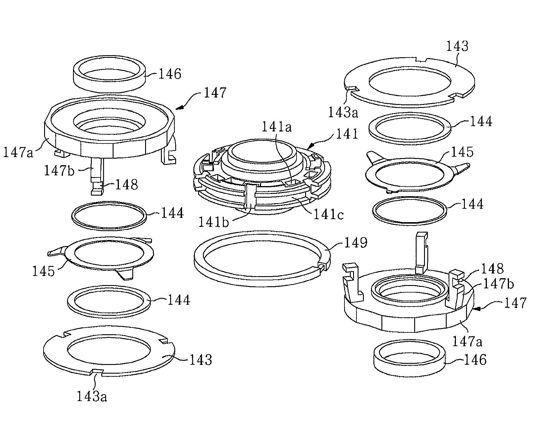
[0023]FIG. 5 illustrates a floating piston valve of an amplitude selective shock absorber according to one embodiment, FIG. 6 is a partial cross-sectional view of the floating piston valve of FIG. 5, and FIG....


PUM


Abstract

A floating piston valve includes an annular valve body having a fluid passing hole formed therein, a pair of upper and lower valve discs respectively mounted on upper and lower sides of the valve body to generate damping force, a pair of upper and lower tripod type leaf valve springs respectively mounted on upper and lower sides of the upper and lower valve discs, and a pair of upper and lower coupling supports coupled to the valve body respectively at upper and lower sides of the upper and lower tripod type leaf valve springs. Each of the coupling supports includes an annular support section and a coupling section at least partially formed on an outer edge of the annular support section and is fastened to the valve body through a portion of an outer edge of the valve body.

Description

BACKGROUND[0001]1. Technical Field[0002]The present disclosure relates to a floating piston valve of a shock absorber damping vibrations transmitted from a road surface to a vehicle and, more particularly, to a floating piston valve of an amplitude selective shock absorber that provides a low-damping force characteristic in response to input of high frequency vibrations, which have low amplitudes and occur frequently, thereby enhancing ride comfort of a vehicle.[0003]2. Description of the Related Art[0004]In general, a vehicle is provided with a suspension system for enhancing ride comfort by absorbing or relieving impacts or vibrations transmitted from a road surface to an axle while traveling on the road. One component of the suspension system is a shock absorber. The shock absorber is disposed between the axle and a vehicle body, and includes a cylinder and a piston rod reciprocating in the cylinder. The cylinder is filled with a damping fluid such as gas or oil, which is moved b...

Claims


Application Information

Patent Timeline
Patent Type & Authority Patents(United States)
IPC IPC(8): F16F9/34
CPCF16F9/5126F16F9/34
Inventor JI, YOUNG CHUNPARK, KYUNG WON
Owner HL MANDO CORP
Features
  • R&D
  • Intellectual Property
  • Life Sciences
  • Materials
  • Tech Scout
  • Unparalleled Data Quality
  • Higher Quality Content
  • 60% Fewer Hallucinations
Learn More