
Small joint orthopedic implants and their manufacture

a small joint, orthopedic technology, applied in the field of small joint orthopedic implants, can solve the problems of inability to perfectly fit a given patient, difficult to manufacture, and difficult to use, so as to avoid complex procedures, facilitate installation, and large stock of standardized implants

Active Publication Date: 2013-01-15
SEITZ JR WILLIAM H +1
View PDF23 Cites 4 Cited by
  • Summary
  • Abstract
  • Description
  • Claims
  • Application Information

AI Technical Summary

Benefits of technology

The present invention is a method for manufacturing small joint orthopedic implants using standard radiographs. By referring to these images and comparing them with a specialized marker, the dimensions of the bone can be accurately determined, allowing for the production of an implant that replicates the original bone. This method avoids the need for a surgeon or hospital to maintain a large inventory of standardized implants and reduces the complexity of the procedure, resulting in quicker surgeries and minimal recovery time. The implant also has the capability for rotation and axial adjustments, allowing for easy installation.

Problems solved by technology

Due to their size and rigidity, these “off-the-shelf” implants often require excessive bone resection to allow their insertion and are technically demanding to use.
The difficulties associated with monoblock implants have led to the development of modular implants in which differently sized heads are fitted to differently sized stems.
Unfortunately, as the length of the head increases, typically so does the diameter, and it is unlikely that any combination of modular parts will perfectly fit a given patient.
A skilled surgeon can adapt such off-the-shelf implants to fit the anatomy of an acute fracture, but it is not uncommon that even in experienced hands an implant does not achieve a desired level of stability.
There are a number of techniques whereby implants are sized to fit a particular patient, but such techniques are exceedingly difficult and expensive to accomplish.

Method used


Image

  • Small joint orthopedic implants and their manufacture
  • Small joint orthopedic implants and their manufacture
  • Small joint orthopedic implants and their manufacture

Examples


Embodiment Construction

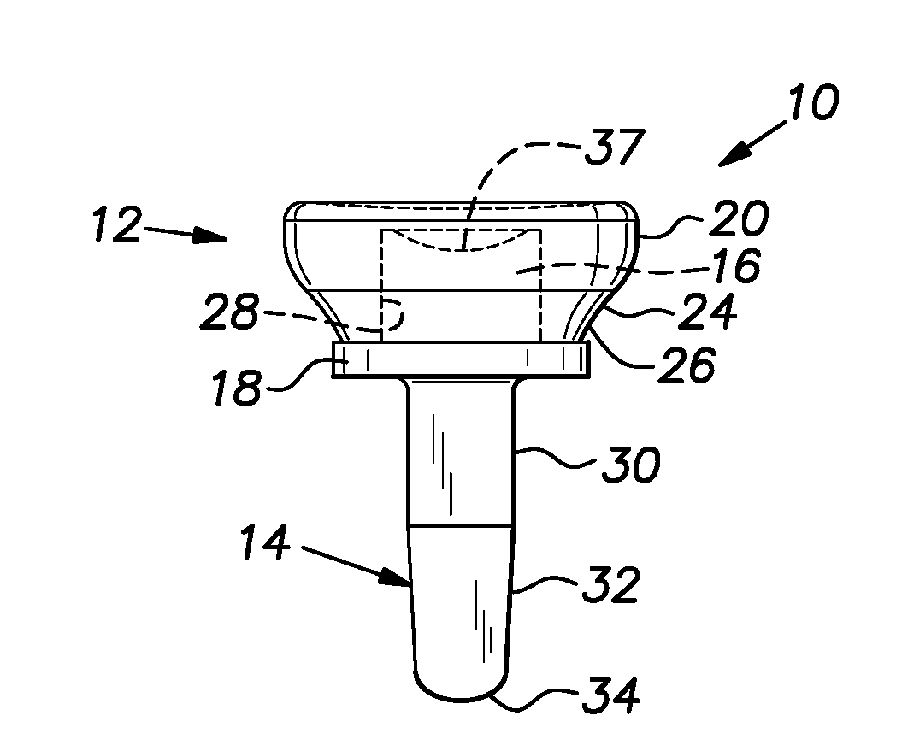
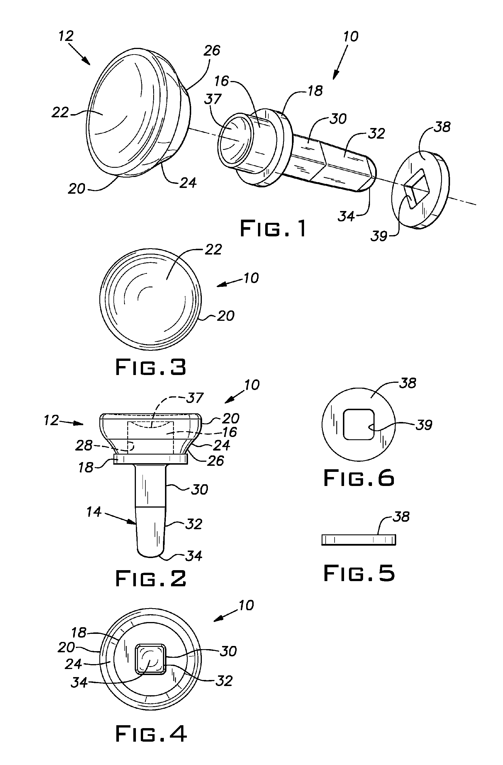
[0033]Referring to FIGS. 1-4, an implant according to the invention is indicated generally by the reference numeral 10. The implant 10 as described herein is intended for radial head replacement, but it is to be understood that suitable modifications in size and shape as will be apparent to those skilled in the art will permit the implant 10 to be used for other types of small joints, such as ulnar head, basal thumb, and the like. It is expected that the implant 10 will be made of surgical grade stainless steel, although the use of other materials is possible.

[0034]The implant 10 includes a head 12 and a stem 14. A post 16 projects from the stem 14 along the longitudinal axis of the stem 14. A radially extending collar 18 is disposed at the intersection between the stem 14 and the post 16. The head 12 includes a generally cylindrical sidewall 20, a concave end face 22, a tapered portion 24 that tapers from a larger dimension at the intersection with the sidewall 20 to a smaller dime...


PUM


Abstract

A technique to manufacture small joint orthopedic implants includes the steps of taking standard radiographs of a pathologic joint and the corresponding non-pathologic joint. In order to provide an accurate frame of reference, a specialized marker is placed in the radiographic field. By inspection of the radiographs and by comparison with the marker, the dimensions of the cortical bone and the cancellous bone can be quickly and accurately determined. These dimensions can be used to manufacture a suitable implant and installation tool. Typically, the implant will include a stem from which a post projects. A radially extending collar is located at the intersection between the stem and the post. A mating head is attached to the post. The head closely approximates the size and shape of the natural head being replaced. The stem will be non-round in cross-section to prevent rotation of the stem in the bone. For many applications, the head will not be fixedly attached to the post, but will be rotatable about the longitudinal axis of the post. One or more spacers that fit about the stem also can be provided in order to adjust the distance that the head projects from the bone.

Description

CROSS REFERENCE TO RELATED APPLICATION[0001]This application claims priority to U.S. provisional application No. 60 / 607,473, entitled SMALL JOINT ORTHOPEDIC IMPLANTS AND THEIR MANUFACTURE, filed Sep. 3, 2004.BACKGROUND OF THE INVENTION[0002]1. Field of the Invention[0003]The invention relates to small joint orthopedic implants and, more particularly, to a technique for the manufacture of such implants that is exceedingly efficient and which eliminates the need for a hospital or surgeon to acquire and maintain an inventory of such implants.[0004]2. Description of the Prior Art[0005]Current methods of small joint orthopedic implant manufacture involve the fabrication of a universal set of sizes of implants, which are sold or consigned to hospitals along with accompanying instrumentation. Because the implants are manufactured to pre-determined specifications, the surgical procedure necessarily requires that the patient's bone be configured to fit a standard implant. This procedure has ...

Claims


Application Information

Patent Timeline
Patent Type & Authority Patents(United States)
IPC IPC(8): A61F2/30
CPCA61F2/3804A61F2/4605A61F2/4606A61B5/107A61F2/42A61F2002/30354A61F2002/30616A61F2002/3827A61F2002/3831A61F2002/4233A61F2002/4253A61F2220/0033A61F2310/00017A61B5/4528A61F2/30942
Inventor SEITZ, JR., WILLIAM H.SANTILLI, ALBERT N.
Owner SEITZ JR WILLIAM H
Learn More