Case-integrated connector

a connector and integrated technology, applied in the direction of electrical equipment, coupling device connections, coatings, etc., to achieve the effect of preventing the clearance of the fitting

Active Publication Date: 2013-02-26
SUMITOMO WIRING SYST LTD
View PDF6 Cites 3 Cited by
  • Summary
  • Abstract
  • Description
  • Claims
  • Application Information

AI Technical Summary

Benefits of technology

[0008]There is a concern that molten resin may intrude through a clearance between two assembled members of a connector that is used as an insert and may flow into the interior of the connector when injection pressure of the molten resin acts on the outer periphery of the connector. However, the connector of the present invention has the annular projection formed over the entire periphery on one of the facing surfaces of the receptacle and the connecting portion that constitutes the fitting. The projection contacts the other facing surface and blocks the flow of the molten resin so that the molten resin cannot intrude through the clearance and into the interior portions of the connector beyond the annular projection. Accordingly, the connector can be used as an insert and the case body can be molded around parts of the connector with risk of molten resin flowing through the fitting and into the first housing due to injection pressure of the molten resin injected into a mold.
[0010]Even when the second housing is made up of plural sub-housings without being formed unitarily in this way, the annular projection can be formed by connecting the individual ribs end to end. Therefore an effect as the annular projection of the invention is exhibited, i.e. the flow of molten resin into the clearance of the fitting is prevented.

Problems solved by technology

There is a concern that molten resin may intrude through a clearance between two assembled members of a connector that is used as an insert and may flow into the interior of the connector when injection pressure of the molten resin acts on the outer periphery of the connector.

Method used


Image

  • Case-integrated connector
  • Case-integrated connector
  • Case-integrated connector

Examples


Embodiment Construction

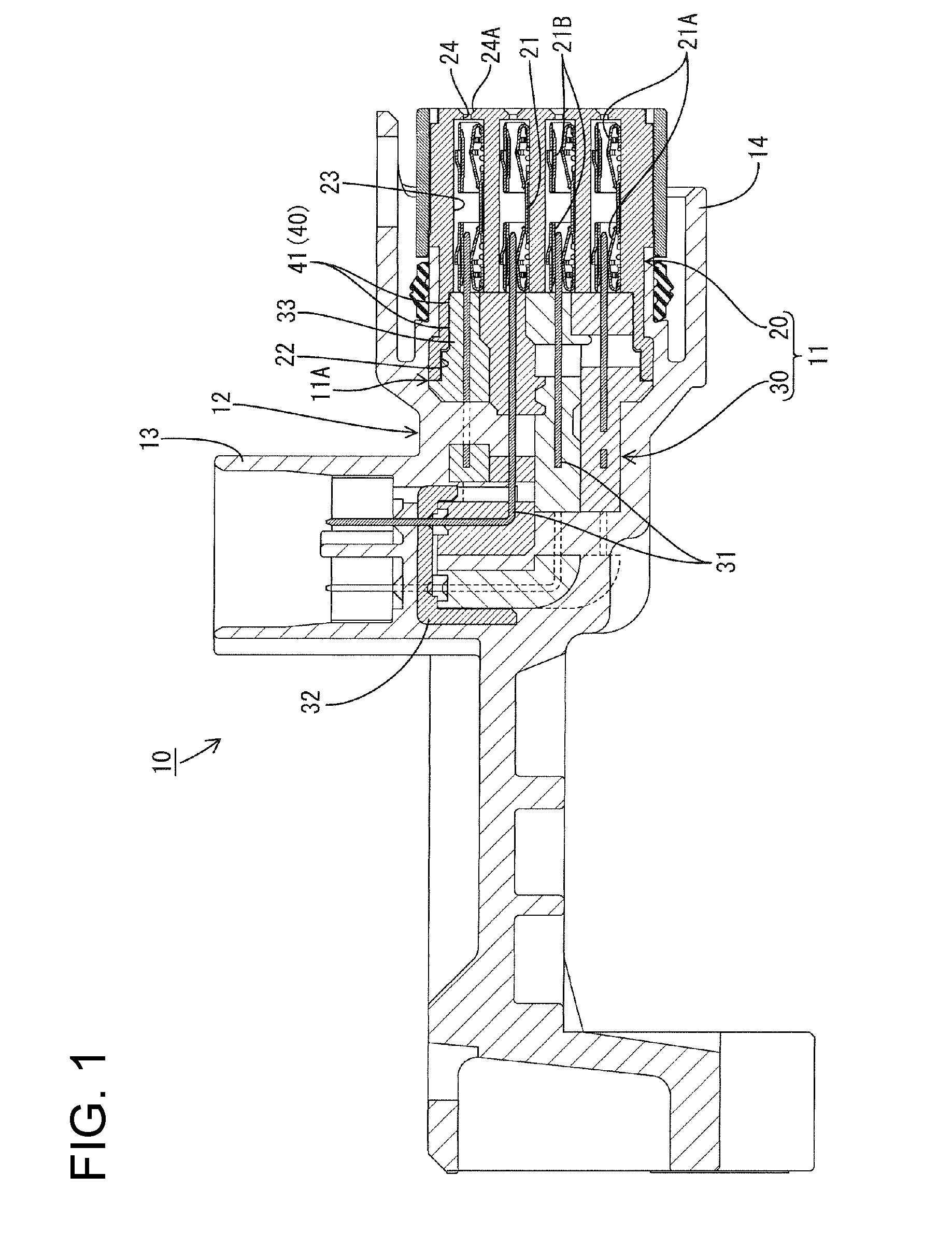
[0029]One specific embodiment of the present invention is described with reference to FIGS. 1 to 12. A case-integrated connector 10 according to this embodiment is applied to a relay connector mounted in an automatic transmission of an automotive vehicle, and a case body 12 that at least partly covers the outer periphery of a connector 11 is formed by insert molding using the connector 11 as an insert. In the following description, respective directions are based on FIG. 1 and left and right sides of FIG. 1 are referred to as front and rear sides and a direction from the front side to the rear side of the plane of FIG. 1 is referred to as a width direction.

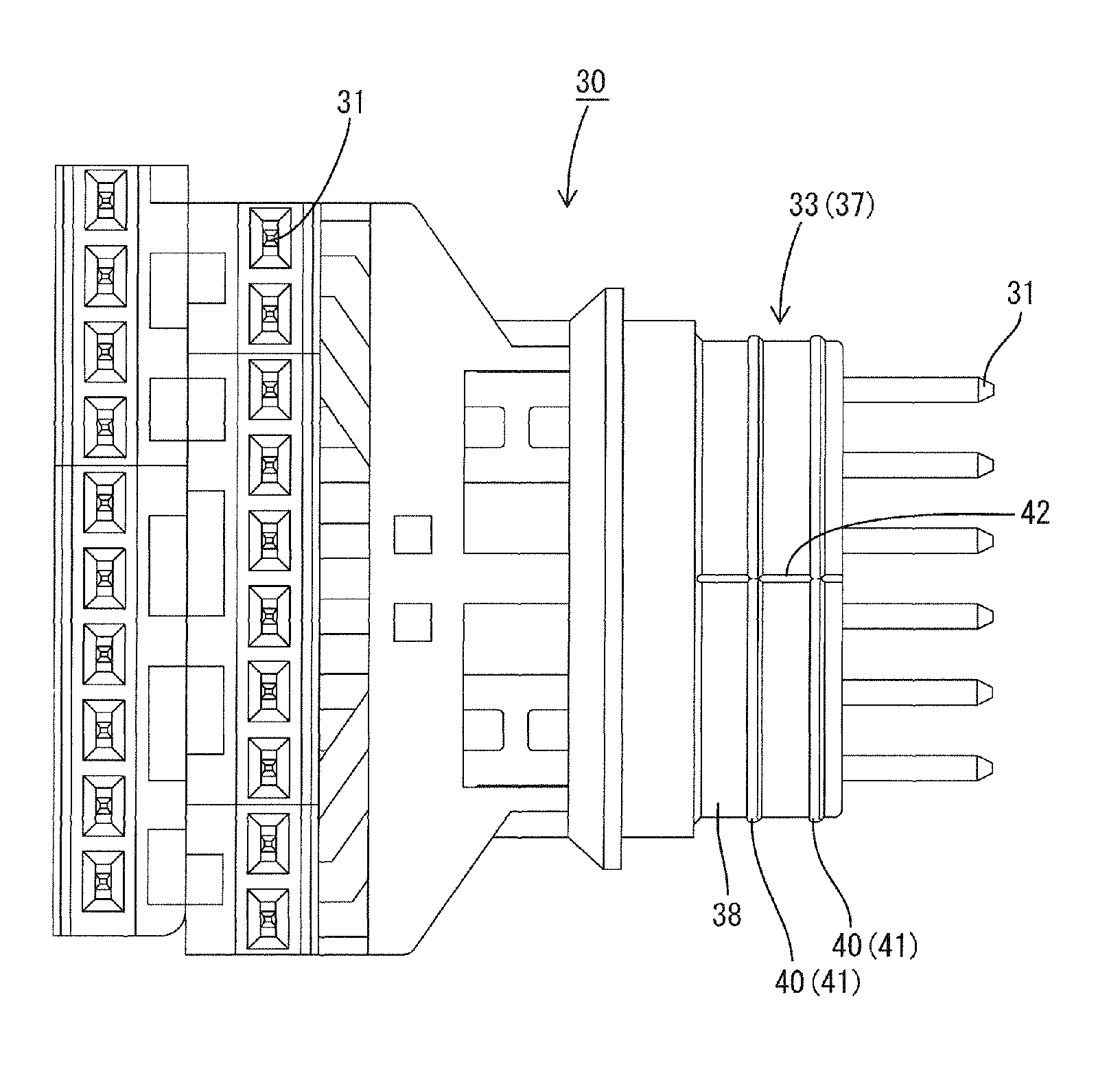
[0030]As shown in FIG. 1, The connector 11 is integrated by fitting a main body 30 that holds male terminal fittings 31 into a relay terminal holder 20 that accommodates female relay terminals 21 from behind. An alignment plate 32 is mounted near an upper end of the main body 30 at a position spaced from the relay terminal holder ...


PUM


Abstract

A case-integrated connector (10) is such that a connector (11) is integrally assembled into a resin-made case body (12) by insert molding using the connector (11) as an insert. The connector (11) is provided with a first housing (20) including a receptacle (22) at one end and a second housing (30) including a connecting portion (33) to be fit into the receptacle (22). The case body (12) covers the outer peripheral surface of a fitting portion (11A) in which the receptacle (22) of the first housing (20) and the connecting portion (33) of the second housing (30) face each other. One of facing surfaces of the receptacle (22) and the connecting portion (33) is formed with annular projections (40) that project outward over the entire periphery to be held in contact with the other facing surface.

Description

BACKGROUND OF THE INVENTION[0001]1. Field of the Invention[0002]The invention relates to a case-integrated connector in which a connector housing is integrally assembled into a case body.[0003]2. Description of the Related Art[0004]Japanese Unexamined Patent Publication No. 2006-315280 discloses a conventional case-integrated connector in which a connector housing is assembled integrally into a case body. This case-integrated connector includes a connector, and a case body that covers the entire peripheral surface of a housing of the connector. The housing includes a main body for holding a busbar and a relay terminal holder for accommodating female relay terminals. A receptacle is provided at one end of the relay terminal holder and communicates with cavities for accommodating the relay terminals. The busbar and the relay terminals are connected by fitting the main body into the receptacle.[0005]The above-described case-integrated connector is formed by insert-molding the case body...

Claims


Application Information

Patent Timeline
Patent Type & Authority Patents(United States)
IPC IPC(8): H01R13/502
CPCH01R43/24H01R13/504B29C45/14639
Inventor ANDO, MOTOHIRONAGASHIMA, SHINYU
Owner SUMITOMO WIRING SYST LTD
Why Eureka
Try Eureka