Mandrel rod damping structure

A component and shaft hole technology, applied in the structural field of restraining shaft rod vibration, can solve problems such as unsolved vibration, and achieve the effect of good position accuracy

Inactive Publication Date: 2011-06-15
LITE ON OPTO TECH (CHANGZHOU) CO LTD +2
View PDF1 Cites 0 Cited by
  • Summary
  • Abstract
  • Description
  • Claims
  • Application Information

AI Technical Summary

Problems solved by technology

[0006] It can be seen from the structure disclosed in this patent that when the vibration generated by the motor running is transmitted to the shaft, it will cause instantaneous vibration of the shaft in the axial direction and other directions, but the structure only solves the instantaneous vibration of the shaft in the axial direction. Doesn't solve vibrations in other directions

Method used


Image

  • Mandrel rod damping structure
  • Mandrel rod damping structure
  • Mandrel rod damping structure

Examples


Embodiment Construction

[0026] The aforementioned and other technical contents, features and effects of the present invention will be clearly presented in the following detailed description of two preferred embodiments with reference to the accompanying drawings.

[0027] Before the present invention is described in detail, it should be noted that in the following description, similar components are denoted by the same reference numerals.

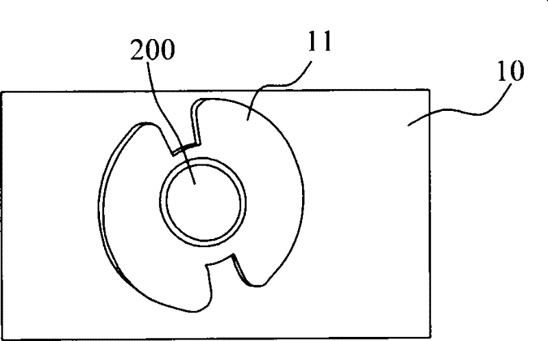
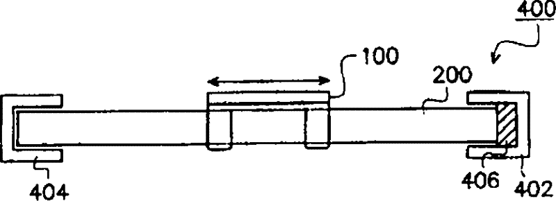
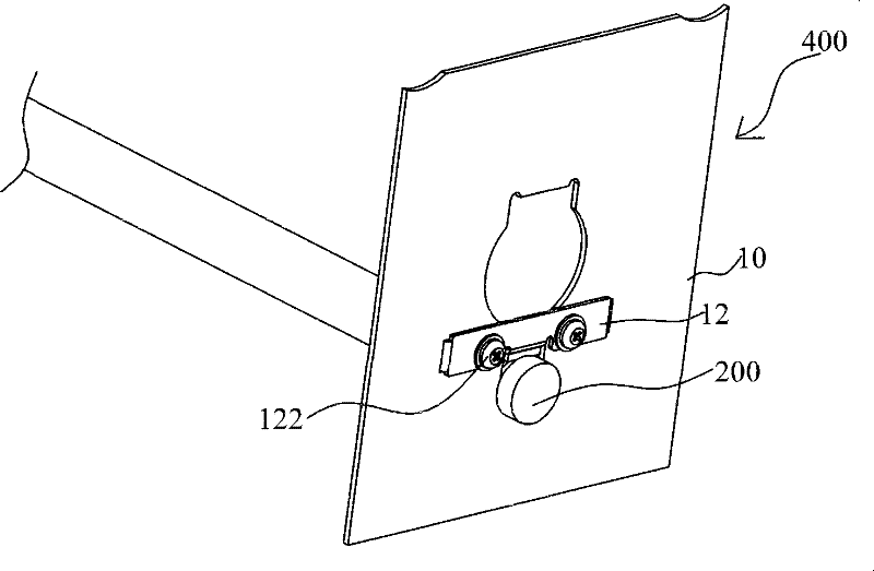
[0028] Figure 2a It is an installation diagram of a preferred embodiment of the present invention. Such as Figure 2a As shown, a preferred embodiment of the present invention discloses a shaft damping structure 400 , the shaft damping structure 400 mainly includes a housing 10 and a pressing member 12 . Wherein, the pressing member 12 is connected to the housing 10 through screws or rivets, and is forced to fix the shaft rod 200 installed on the housing 10 .

[0029] It should be noted that the screw connection is taken as an example below, and its replacemen...


PUM


Abstract

The invention provides a mandrel rod damping structure for reducing the shake of a mandrel rod. The mandrel rod is sleeved with a scanner and a scanning module, and the scanning module can reciprocatealong the mandrel rod which is arranged in a shaft hole. The mandrel rod damping structure is characterized in that a part of the shaft hole, which bears the mandrel rod, is in a V-shaped structure and provided with a fastening component for fixing the mandrel rod, and the mandrel rod is supported by the V-shaped structure which is in point contact with the mandrel rod so as to better control theposition precision of the mandrel rod; the mandrel rod is contacted with an elastic component made of rubber materials and pressed by a rigid fastening component so as to keep in a gapless state allthe time, thus the problem of the assembly gap of the mandrel rod can be effectively solved, and the elastic component made of the rubber materials can damp the shake. The mandrel rod damping structure can solve a plurality of image problems due to great shakes along a circumferential direction of the mandrel rod and no scanning module deviation in the scanning process.

Description

technical field [0001] The invention relates to a shock-absorbing structure of a scanner, in particular to a structure for suppressing the vibration of a shaft rod. Background technique [0002] Usually, when the scanning module of the flatbed scanner scans the document on the light-transmitting plate, the optical scanning module scans along the scanning direction through a transmission device. The transmission device has a stepping motor and is connected with the scanning module by using a belt and a pulley. [0003] Such as Figure 1a As shown, a general scanner has a rod 200 in its transmission structure, and the scanning module can linearly reciprocate along the rod 200 . Both ends of the shaft are fixed on a frame 10 of the scanner, and a washer 11 is provided on the shaft end to tighten the shaft and maintain a certain stability. [0004] However, due to the gap between the shaft and the housing, and the vibration of the shaft caused by the power transmission of the ...

Claims


Application Information

Patent Timeline
Patent Type & Authority Patents(China)
IPC IPC(8): H04N1/14
Inventor 雷艳荣黄兆华
Owner LITE ON OPTO TECH (CHANGZHOU) CO LTD
Why Eureka
Try Eureka