Positioning fixture for pile foundation reinforcement cage

A pile foundation reinforcement cage and positioning fixture technology, applied in sheet pile walls, infrastructure engineering, structural elements, etc., can solve the problems of collision, increase the thickness of hole slag, and the thickness of steel protection layer is different, so as to avoid The effect of damage, sufficient strength, and uniform thickness

Pending Publication Date: 2020-09-25
CHINA MCC5 GROUP CORP
View PDF0 Cites 0 Cited by
  • Summary
  • Abstract
  • Description
  • Claims
  • Application Information

AI Technical Summary

Problems solved by technology

This method has the following disadvantages: 1. The manufacturing process of the reinforcement cage requires welding lugs and binding of concrete pads, and the material is one-time access, which is not conducive to saving construction costs; The hole wall collides, increasing the thickness of the slag deposited in the hole
3. It is not conducive to ensuring that the reinforcement cage remains perpendicular to the center of the pile hole during the lowering process, resulting in different thicknesses of the reinforcement protection layer

Method used


Image

  • Positioning fixture for pile foundation reinforcement cage
  • Positioning fixture for pile foundation reinforcement cage

Examples


Embodiment 1

[0017] In this embodiment, a positioning fixture for a reinforcement cage of a pile foundation includes a fence that can be arranged in the pile hole, and a through hole for passing the reinforcement cage is arranged in the fence.

[0018] During construction, install the fence at the entrance of the pile hole, hoist the reinforcement cage and align the reinforcement cage with the through hole of the fence, then put down the reinforcement cage, and use the fence to limit and guide the reinforcement cage, so that Avoid contact between the reinforcement cage and the inner wall of the pile hole, and limit the reinforcement cage to the range covered by the through hole, so that the distance between the reinforcement cage and the inner wall of the pile hole remains constant, which is conducive to making the thickness of the concrete protective layer uniform and reach the design target. required requirements.

Embodiment 2

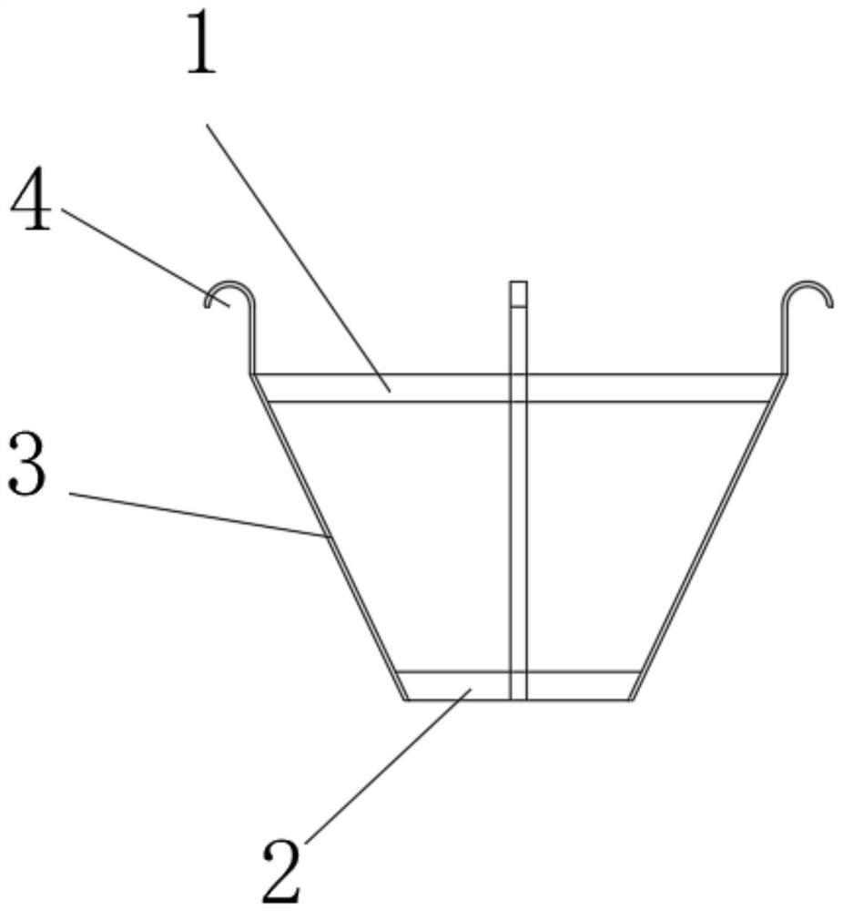
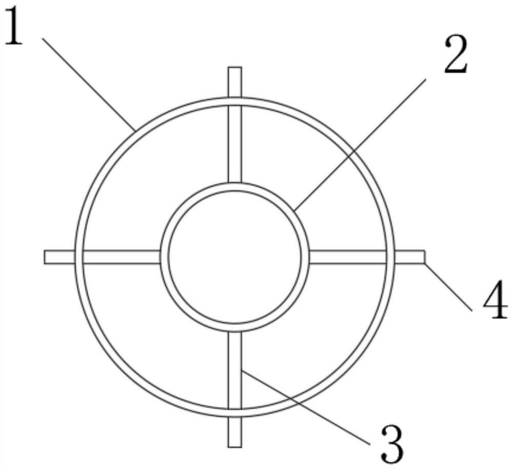
[0020] Such as figure 1 , figure 2 As shown, on the basis of the above embodiments, in this embodiment, the fence includes A limit ring 1 and B limit ring 2 arranged below A limit ring 1, A limit ring 1 and B limit ring A connection structure is provided between the bit rings 2 . A limit ring 1 and B limit ring 2 are used to guide and limit the reinforcement cage. A limit ring 1, B limit ring 2 and the connection structure form a frame structure, which can reduce the weight of the fence. Thereby, the pressure of the fence on the pile hole is reduced, and the pressure damage at the entrance of the pile hole is avoided.

[0021] In this embodiment, the diameter of the A limiting ring 1 is larger than the diameter of the B limiting ring 2, and the A limiting ring 1 and the B limiting ring 2 are coaxial. In this way, the maximum outer diameter of the A limiting ring 1 can be matched with the inner diameter of the pile hole, and the gap between the A limiting ring 1 and the inn...


PUM


Abstract

The invention discloses a positioning fixture for a pile foundation reinforcement cage. The positioning fixture for the pile foundation reinforcement cage comprises a fence which can be arranged in apile hole, wherein a through hole allowing the reinforcement cage to pass through is formed in the fence. The positioning fixture for the pile foundation reinforcement cage has the beneficial effectsthat by means of the scheme, the position and the moving direction of the reinforcement cage can be limited, so that the position accuracy in the installation process of the reinforcement cage is controlled, the reinforcement cage is prevented from shaking to be in contact with the inner wall of the pile hole, and the inner wall of the pile hole is prevented from being damaged; besides, the distance between the reinforcement cage and the inner wall of the pile hole can be kept consistent all the time, so that the thickness uniformity of a concrete protective layer is guaranteed, and the strength of the concrete protective layer meets the design requirement.

Description

technical field [0001] The invention relates to the technical field of pile foundation construction, in particular to a positioning clamp for a pile foundation reinforcement cage. Background technique [0002] Pile foundations are widely used in engineering construction, and their construction quality will directly affect the safety of subsequent construction. The thickness of the pile foundation reinforcement protective layer is one of the important indicators to ensure the durability of the pile foundation. The pile foundation reinforcement protection layer that meets the design specifications can well block the corrosion of the reinforcement by external air, moisture and other substances, thereby improving the durability of the pile foundation. In most of the pile foundation construction, the method of welding lugs on the steel cage or binding concrete pads is adopted to ensure the thickness of the concrete protective layer of the pile foundation. This method has the fol...

Claims


Application Information

Patent Timeline
Patent Type & Authority Applications(China)
IPC IPC(8): E02D5/34E04C5/18
CPCE02D5/34E04C5/18
Inventor 杨康罗利罗建勋张立云隆玮
Owner CHINA MCC5 GROUP CORP
Why Eureka
Try Eureka