A Miniaturized Laser Synchronous Scanning Triangulation Ranging System

A triangular distance measurement and synchronous scanning technology, which is applied in the direction of measuring devices, optical devices, instruments, etc., can solve the problem that the distance resolution of the horizontal scanning measurement range and the vertical ranging range cannot adapt to the size and distance changes of the measured object, and the structural volume Small and other problems, to achieve the effect of simple structure, small size and fast acquisition

Active Publication Date: 2018-12-07
SHANGHAI UNIV
View PDF6 Cites 0 Cited by
  • Summary
  • Abstract
  • Description
  • Claims
  • Application Information

AI Technical Summary

Problems solved by technology

[0006] The purpose of the present invention is to solve the problem that the horizontal scanning measurement range, longitudinal ranging range, and distance resolution cannot be adjusted to adapt to the size and distance of the measured object in the general laser synchronous scanning triangulation ranging imaging system, and propose a miniaturized laser The synchronous scanning triangulation ranging system can adapt to the synchronous scanning triangulation ranging imaging with different measurement ranges and resolution requirements, and at the same time minimize the structural volume of the laser synchronous scanning triangulation ranging system

Method used


Image

  • A Miniaturized Laser Synchronous Scanning Triangulation Ranging System
  • A Miniaturized Laser Synchronous Scanning Triangulation Ranging System
  • A Miniaturized Laser Synchronous Scanning Triangulation Ranging System

Examples


Embodiment 1

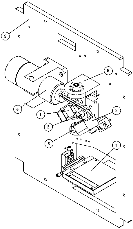
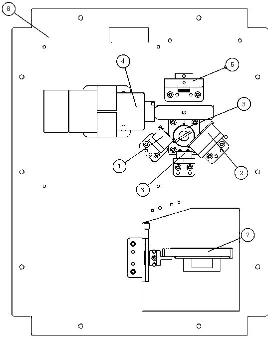
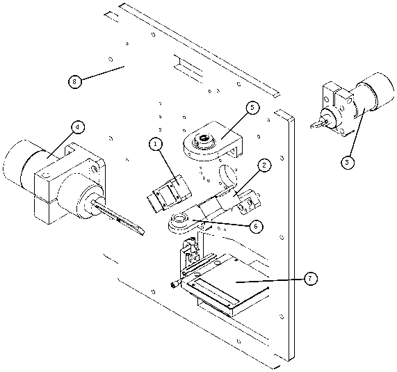
[0044] The miniaturized laser synchronous scanning triangulation ranging system includes M1 mirror part 1, M2 mirror part 2, M3 mirror part 3, M4 mirror part 4, laser part 5, lens part 6, PSD part 7 and base plate 8, and is characterized in that The M3 mirror part 3 is located at the origin of the set space coordinate system, and is vertically fixed on the base plate 8 by hexagon socket bolts; the M1 mirror part 1 and the M2 mirror part 2 are respectively located on the left and right sides of the M3 mirror part 3, and to M3 mirror parts 3 are at the same distance, the angle between M1 mirror part 1 and the horizontal axis is 135°±2°, the angle between M2 mirror part 2 and the horizontal axis is 45°±1°, and they are vertically fixed on the bottom plate 8 by hexagon socket bolts ; The M4 mirror part 4 is vertically fixed on the base plate 8 to ensure that the mirror surface conical hole is located directly above the coordinate origin; the laser part 5, the lens part 6 and the M3...

Embodiment 2

[0046] refer to Figure 4 to Figure 14 , the present embodiment is basically the same as Embodiment 1, and the special features are as follows:

[0047] The M1 mirror component 1 includes an M1 mirror support 9 and an M1 mirror 10, wherein the M1 mirror 10 is a single-sided reflector, and the slot width of the M1 mirror support 9 is slightly larger than the width of the M1 mirror 10 to ensure that the M1 mirror 10 can be placed horizontally on the On the M1 mirror support 9, the M1 mirror 10 is fixed through a cover 10'; the M2 mirror component 2 includes an M2 mirror support 11 and an M2 mirror 12, wherein the M2 mirror 12 is a single-sided mirror, and the M2 mirror support 11 The width of the slot is slightly larger than the width of the M2 mirror 12 to ensure that the M2 mirror 12 can be placed horizontally on the M2 mirror support 11, and the M2 mirror 12 is fixed through a cover piece 12'; the M3 mirror part 3 includes the M3 mirror 13, the M3 mirror vibration Mirror mot...

Embodiment 3

[0056] see Figure 15 , the miniaturized laser synchronous scanning triangulation ranging system of the present invention is as follows:

[0057] 1. Turn on the laser and PSD, adjust the appropriate laser power, the laser energy should not be too weak. Initialize the ranging system, open the galvanometer control software to reset, and make the M3 and M4 mirrors return to the initial angle position;

[0058] 2. The host computer issues instructions to control the swing angle of the vibrating mirror motor. The M3 and M4 mirrors perform reciprocating swing motion around the axis at the same time. The laser scans the raster track on the surface of the measured object, and the diffuse reflection light is focused on the PSD surface by the lens;

[0059] 3. PSD detects the position of the light spot, converts the position information into a voltage value output, and the multi-channel acquisition system simultaneously collects and transmits the voltage value output by the angle sensor ...


PUM


Abstract

The invention relates to a miniature laser synchronous scanning triangulation ranging system, comprising an M1 reflector component, an M2 reflector component, an M3 reflector component, an M4 reflector component, a laser component, a lens component, a PSD component and a base plate. The collimated laser beam emitted by a laser is reflected by the upper reflection surface of a double-faced reflector M3, a reflector M1, and a reflector M4 to reach a certain point Q on a tested curved surface and to perform diffuse reflection; partial diffuse reflection light is reflected by the reflector M4 and the lower reflection surface of the double-faced reflector M3, and gathers light spots on the surface of a PSD through a lens; the PSD collects light spot position information and outputs a voltage value; a multi-channel collection system simultaneously collects voltage values outputted by an angle sensor and the PSD, and transmits the voltage values to an upper computer; after calculation of the upper computer, space point position coordinates are obtained. The system has a measuring distance range of 0.5 m-10 m, and has the advantages of high measurement precision, real-time collection and small system structure size.

Description

technical field [0001] The invention is mainly used in the field of optical non-contact precision measurement, and relates to a miniaturized laser synchronous scanning triangulation ranging system, which can be used to measure the three-dimensional surface shape of an object, and can meet the requirements of different measurement ranges and resolutions. Background technique [0002] With the advancement of science and technology, the field of industrial measurement is constantly developing, and the requirements for measurement technology are getting higher and higher. The traditional contact 3D measurement is deformed due to the contact with the measured object, which causes errors, affects the measurement accuracy, and mainly damages the surface of the object, wears the contact head, and is slow, which can no longer meet the needs of modern industrial development. Optical non-contact three-dimensional measurement is a method to scan the space and structure of the object to ...

Claims


Application Information

Patent Timeline
Patent Type & Authority Patents(China)
IPC IPC(8): G01B11/02
CPCG01B11/02
Inventor 张旭杨浩
Owner SHANGHAI UNIV
Why Eureka
Try Eureka