

Double head lathe for hydraulic conduit
A duct and double-head technology is applied in the field of special double-head lathes for hydraulic ducts, which can solve the problems of high labor intensity, many waste products, and many times of clamping, and achieve the effects of improving production efficiency, reducing waste products, and improving product quality.
- Summary
- Abstract
- Description
- Claims
- Application Information
AI Technical Summary
Problems solved by technology
Method used
Image

Examples
Embodiment Construction
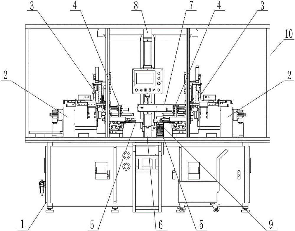
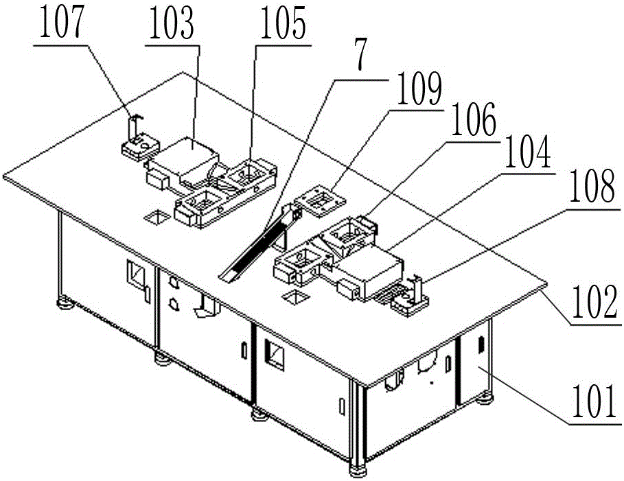
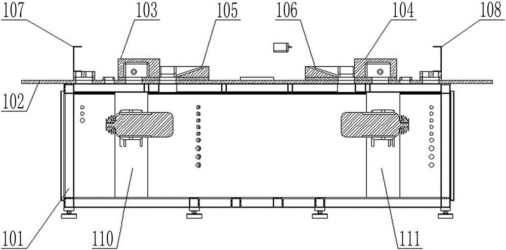
[0046] Depend on figure 1 It can be seen that the special double-headed lathe for hydraulic conduits of the present invention includes a frame assembly 1, and the transmission boxes 2 on the left and right sides with the same structure are arranged opposite to each other on the frame assembly 1, and elastic clips are installed on the main shaft of each transmission box 2. Claws 203, X-direction knife rest, Y-direction knife rest, Z-direction knife rest 3 and feeding device 4 are all installed on the frame assembly 1 close to the elastic jaws 203, and the bottom of feeding device 4 is provided with a material receiving device 5, The frame assembly 1 between the feeding devices 4 on the left and right sides is provided with an intermediate transition frame 6, and the rear of the feeding device 4 on the right is provided with a parallel belt conveying device 7, and the frame assembly 1 behind the parallel belt conveying device 7 A control box support 8 is arranged on the top, and...
PUM
 Abstract
Description
Claims
Application Information