Protective arrangement for the protection of safety-relevant electronic circuits from malfunctions

a technology of electronic circuits and protective arrangements, applied in the direction of braking action transmission, reflectors, analog computers, etc., can solve the problems of unintended activation of electrically controlled components, inadequate protection of protection facilities described therein, etc., and achieve the effect of preventing the critical effects of such short-circuits and facilitating continuous monitoring

Active Publication Date: 2013-04-02
LUCAS AUTOMOTIVE GMBH
View PDF20 Cites 0 Cited by
  • Summary
  • Abstract
  • Description
  • Claims
  • Application Information

AI Technical Summary

Benefits of technology

[0008]The present invention is directed toward a protective arrangement for the protection of safety-relevant electronic circuits from malfunctions is described below. It is based on the self-monitoring principle and facilitates the continuous monitoring of important operating parameters, such as—for example—voltage in the electronic circuit, thus enabling impending faults to be detected at an early stage. By using protective elements for the early detection of short-circuits between tracks on a printed circuit board, critical effects of such short-circuits are prevented wherein the protective elements are to be implemented directly on the printed circuit board.
[0009]On the basis of the above-stated problem, a protective arrangement is to be specified that is simple and cost-effective to implement.

Problems solved by technology

Short-circuits on such printed circuit boards or in a multilayer circuit board may lead to malfunctions.
For example, short-circuits caused by moisture penetrating the housing of the electronic circuit, may result in the unintended activation of an electrically controlled component.
This problem is becoming apparent more frequently in view of the increasing electronification of motor vehicles.
However, if a number of short-circuits occur in parallel, the protection facilities described therein do not provide adequate protection.

Method used


Image

  • Protective arrangement for the protection of safety-relevant electronic circuits from malfunctions
  • Protective arrangement for the protection of safety-relevant electronic circuits from malfunctions
  • Protective arrangement for the protection of safety-relevant electronic circuits from malfunctions

Examples


Embodiment Construction

[0076]The transistors described below are, in particular, n-channel high-side field-effect transistors. Field-effect transistors, because of their large input resistor, permit power-free control of a current by a voltage. Consequently, the control of a component which is controlled by one of the transistors described below is generally power-free. However, other semiconductor switches may be protected with the proposed protective arrangement.

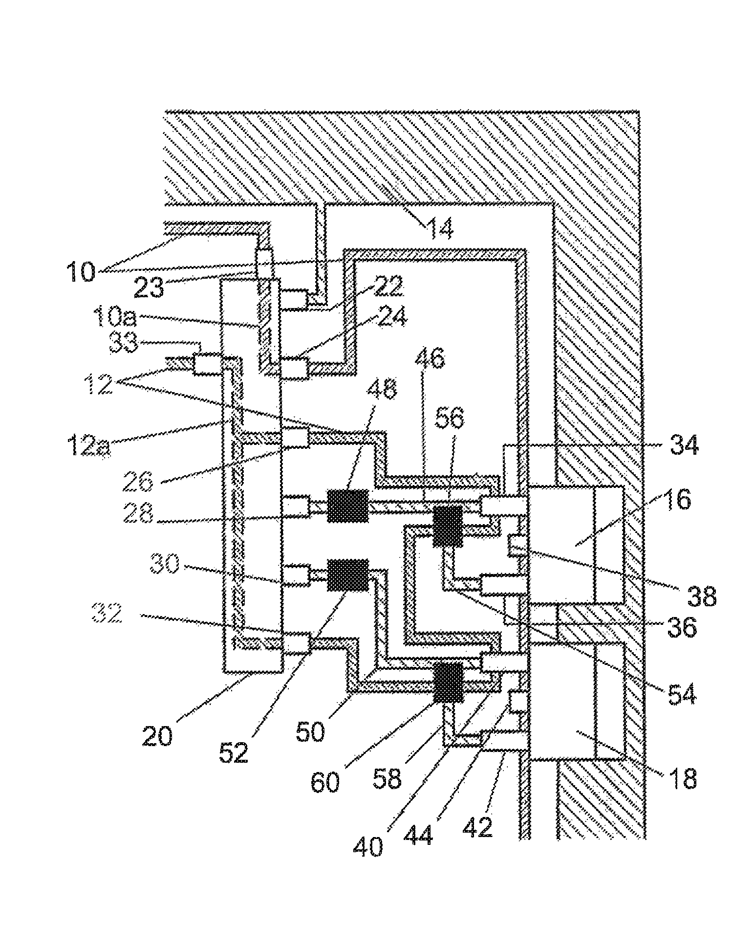
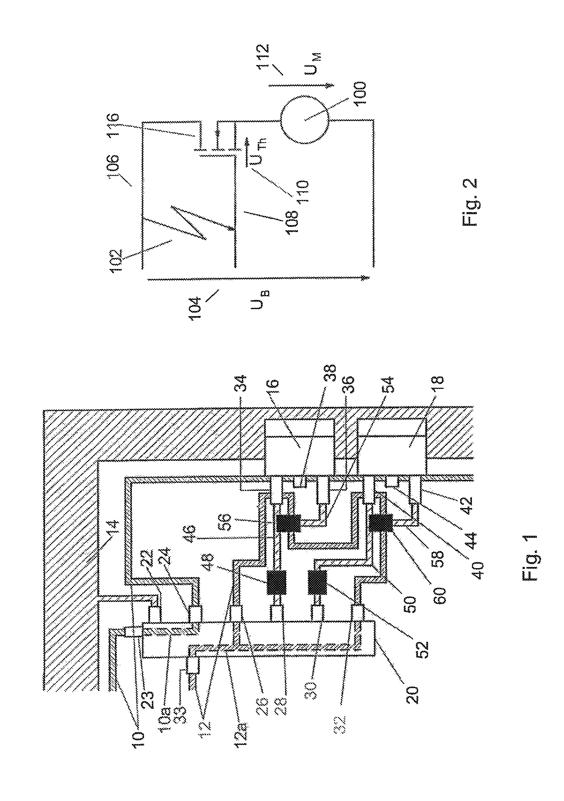
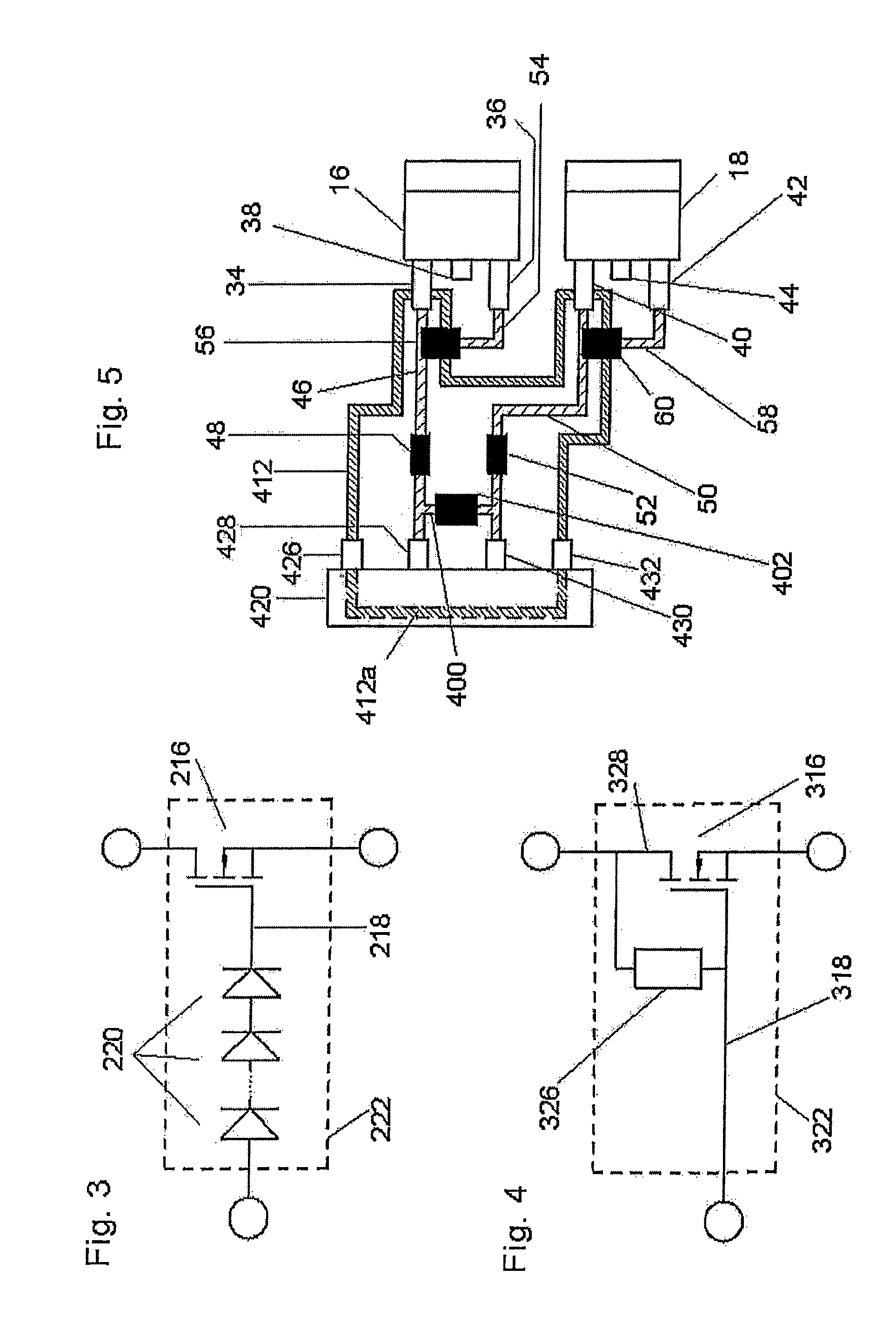
[0077]FIG. 1 shows a section of a printed circuit board on which a passive protective circuit is arranged. It includes two conductor loops 10, 12. Both conductor loops 10, 12 have an earth potential.

[0078]A section of a supply voltage track 14, two transistors 16, 18 and a driver module 20, are also arranged on the section of the printed circuit board.

[0079]Eight terminals of the driver module 20 are relevant for the embodiment described below; a supply voltage terminal 22, two conductor loop terminals 23, 24 for the first conductor loop 10, thr...


PUM


Abstract

A protective circuit arranged on a Printed Circuit Board (PCB) has two conductor loops. At least one supply voltage track, at least one semiconductor switch and at least one control component are arranged on the PCB. A first terminal of the control component and a first terminal of the semiconductor switch are connected electrically. A first conductor loop of the protective circuit is arranged on the PCB so that it surrounds an electrically conducting connection between the supply voltage track and the semiconductor switch and / or the control component. A second conductor loop is arranged on the PCB so that it surrounds the electrically conducting connection between the first terminal of the control component and the first terminal of the semiconductor switch, and thereby screens the same from the semiconductor switch and at least from those regions of the control component that are also connected to the supply voltage track.

Description

CROSS-REFERENCE TO RELATED APPLICATIONS[0001]This application is a national stage of International Application No. PCT / EP2009 / 002765 filed Apr. 15, 2009, the disclosures of which are incorporated herein by reference, and which claimed priority to German Patent Application No. 10 2008 019 673.8 filed Apr. 18, 2008, the disclosures of which are incorporated herein by reference.BACKGROUND OF THE INVENTION[0002]Printed circuit boards or multilayer circuit boards (which comprise several printed circuit boards in layers) are used in many electronic devices. A printed circuit board is a support made of insulating material with adherent conducting connections. It is used for the mechanical fixing and electrical connection of electronic circuit components and parts. Integrated circuits can be placed directly on or in the printed circuit board. In a multilayer circuit board, such printed circuit boards are connected to each other electrically and / or mechanically.[0003]Short-circuits on such p...

Claims


Application Information

Patent Timeline
Patent Type & Authority Patents(United States)
IPC IPC(8): B60T13/74H02H3/00
CPCB60T13/746G01R31/025G01R31/2818H05K1/0265H05K1/0268H05K2201/09781H05K2201/10053H05K2201/10166G01R31/52
Inventor FUCHS, MATTHIASJUNGLAS, MARCOMUDERS, LUTZOHLIG, BENEDIKT
Owner LUCAS AUTOMOTIVE GMBH
Why Eureka
Try Eureka